GPIO Measurement Circuit
To perform data acquisition from the GPIO ports integrated into the Raspberry Pi 4, we designed and built an MCP3008-based ADC circuit on the NI Elvis II Test Platforms located in Urbauer 115. The connection diagram for the MCP3008 and Pi 4 GPIO is illustrated below:
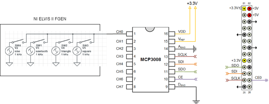
Clarifications on port abbreviations are provided below:
- VDD signifies the supply voltage used for the MCP3008 Analog-to-Digital Converter. Similarly, VREF is the reference voltage used by the MCP3008 for converting analog inputs into digital outputs.
- SCLK is the serial clock signal supplied to the MCP3008 by the Raspberry Pi 4.
- SDO stands for “Serial Data Out”; data moves from the sensor, in this case the MCP3008, to the Pi 4.
- SDI stands for “Serial Data In”; data moves from the Pi 4 to the MCP3008.
- SW1-4 denotes the input signals fed into the circuit for testing. We tested sine, sawtooth, triangle and square wave inputs at frequencies ranging from 0 Hz (DC) to 20 kHz.
More details on the MCP3008
We used the Adafruit MCP3008 16-pin Analog-To-Digital Converter (ADC) for both its performance characteristics and its current use in the ESE department on the ESE 205 Autonomous Pi Car. Picture is shown below:

The maximum sampling rate of the MCP3008 is 200 kHz
, an upper bound unlikely to be exceeded in any ESE department use case. The MCP3008 ADC also acquires 16-bit data, which is a sufficiently high level of precision.
Data Acquisition Methodology
We originally intended to perform data acquisition directly from MATLAB and in real-time. However, we discovered that the computing overhead of simultaneously acquiring, processing and displaying measurements severely limited the maximum effective sample rate to approximately . The issue persisted when we opted for off-line data processing. Referencing all circuit components to the same ground did not remedy the issue, but did remove some noise from the output waveforms.
To work around this constraint, we developed a data processing function in Python 3.7 which runs directly on the Pi 4:
- The function makes use of the Adafruit MCP3xxx Python library, available here: https://github.com/adafruit/Adafruit_CircuitPython_MCP3xxx
- The Python class for the MCP3008 features configurable sample rates, acquisition channels and clock speeds, parameters we tweaked to test data acquisition accuracy.
- The Python script will acquire data from a user-determined ADC Channel (any of CH0 through CH7) and time-period, for example 10 seconds. Since the ADC channel output is a 16-bit value, we implemented an expression to convert it into an analog voltage reading. The data is then saved on the Pi and extracted to the host computer running the MATLAB GUI.
- Since MATLAB cannot run directly on the Raspberry Pi, the data acquisition script must be run indirectly via a command from the platform’s MATLAB GUI. This command is generated in the MATLAB GUI, which will ask the user for the input parameters, synthesize them into an execution script, and run it in the Pi 4’s command shell.
- Once data acquisition is complete, the measurements are saved as a .mat file on the Pi 4. The MATLAB GUI then extracts this .mat file into a user directory designated for storing collected data.
Since Python is a high-level programming language requiring minimal overhead per operation, the bottleneck imposed by the execution of each operation on the MCP3008’s theoretical sample rate
was significantly reduced, and we were able to record high-quality signals at significantly higher input frequencies.
