Project Updates
The project scope, need statement, design schedule, and team responsibilities remain unchanged. The updated Gantt chart can be found in Figure A of the Appendix. The project design has undergone a few changes. Firstly, the U shaped spring that had been originally developed did not have a hard stop point, and the stress overloaded the connection points to the endplates. Therefore, the spring shape has been changed to the more triangular shaped spring that was in the pugh chart of the previous report. Secondly, one side of the springs will no longer be larger in order to account for the curve of the L5/S1 region. This was causing problems as the weight was unevenly distributed along the device. Furthermore, the size difference that the springs would need to have in order to accommodate the 15° curve, did not mathematically allow for them both to have the correct spring constant. Instead, the base plate will be thicker on one end to account for the curvature. Updated CAD designs can be found in Figure B in the Appendix. There have also been some changes to the design specification to reflect further specifications from the client such as MRI compatibility, spring constant and torsion. The amount of compression force that the device must withstand has also been updated. A full list of the design specifications can be found in Table A in the Appendix. Lastly, the project budget has also been updated to reflect the change in cost based on the changes to the design. This updated budget can be found in Table B in the Appendix.
Verification Plan
The verification plan for this project includes a list of tests that will be used to confirm that all of the design specifications of the device have been met by the design team. A table of the design specification and their corresponding verification testing can be found in Table A in the Appendix.
Size: The design specifications indicate that the device must have a midline height of 6.1-10.3 ± 1.0 mm and an angle of curvature 15.3 ± 1.0 degrees anterior-posterior [1]. In a severely diseased disc, the range of motion is 1.0 ± 1.3 mm [2], whereas in an asymptomatic disc, the range of motion is 2.91 ± 2.28 mm [3]. As such, the client defined 2.0 mm as the goal maximum range of motion for the device, since the goal is to restore some of the mobility from a diseased state, but too much change to the intervertebral disc can cause damage to the adjacent vertebra. Furthermore, the design specifications indicate that the size of the endplates should be 26-33 mm by 31-40 mm. To test each of these, the dimensions will be set in the CAD portion of Fusion 360 and once the device is printed, it will be physically measured with a caliper.
Weight: The weight of a natural intervertebral disc is 20 ± 5 g [4], and the design must be approximately equal to, if not on the lower end, of this specification. This will be tested by weighing the physical prototype on a scale and by looking at the weight estimate of Fusion360. Compression: The lumbar disc needs to withstand ≥ 300 N without functional failure to withstand the necessary axial compression of one’s day to day life. An axial compression and Electrodynamic test will be performed with the ADMET device in order to mimic real-world axial compression until functional failure is met. This testing falls under ASTM F2346 [13].
Spring Constant: The design of the lumbar disc must allow for a stiffness/ spring disc that closely replicates the intervertebral disc in the L5-S1 region. As per the design specifications the spring constant should be 71.4 ± 2.0 * 104 N/m [14]. This number is calculated mathematically by dividing the force applied by the distance the disc displaces. This number will be verified by performing FEM testing in Fusion360 and checked by the design team by physically applying a force and measuring the displacement with a caliper.
Shear: The static shear anterior-posterior load must not exceed 700 N, approximately, and must be tested at a 45 degree angle as per the FDA [13] [5]. To mechanically test for the shear limit, a MTE-25 double-column universal testing machine will be utilized, which allows for closed-loop control of force and deformation [6]. It will also be verified by performing FEM testing in Fusion360 in order to ensure that the theoretical shear limits are accurate.
Torsion: The torsional shear must not exceed 1200 N [7]. A cyclic torsion test and a monotonic torsion test will be performed with the ZwickRoell device in order to mimic real-world repeated loading and gradual behavior until the 1200 N deformation level [g] [9].
Degree of Freedom: The purpose of the device is to provide the patient with the same range of motion as a natural, non-diseased disc. In order to ensure that the device allows that, it will be placed into the Bionix Spine Wear Simulator [11] which will test its performance in all possible directions. This is compliant with ASTM F2423 [10].
Ease of surgery: As per the design specifications given by the client, the surgery must cause minimal trauma to adjacent vertebrae and discs and be completed in a single procedure [12]. This is important for both implantation and the retrieval process to ensure the device could be removed safely, if necessary. This will be verified by an experimental trial in which a surgeon attempts to implant this device as well as a Prodisc-L Total Lumbar Disc Replacement (which is the current best option in the market) into cadaver spines. The time of each surgery will be recorded, and ease of surgery will be successful if the implantation of this device takes the same amount of time or less than the Prodisc-L.
Duration: To dynamically test the artificial disc for long term viability, fatigue testing would be performed in a 0.9 % saline environmental bath at 37°C at a rate of 2 Hz or less to simulate what the average person walks for one day. This would then be used to calculate the force that the device would need to withstand in order to last for 13 years and this testing would be performed in the ADMET eXpert 5900 Series Tabletop Dynamic Testing Machine [15]. The device would also need to be tested to comply with ASTM F2346 [13].
Cost: The design specifications indicate that in order to be market competitive, the device must cost less than $10,000 to ensure it can be accessible and offset the surgery costs. This will be verified by ensuring that the cost of printing the prototype is well below that value.
Attachment Method: The device must attach securely to the adjacent vertebrae, as well as support bone growth into the endplates. To test the attachment effectiveness, the device will be utilized in a clinical trial to ensure it does not come dislodged during use. To test the bone growth, the device will be implanted in a pig for 5 months to allow for the full bone remodeling period [16], after which, the implant will be removed, checked for movement within the spine, and tested for compression, shear, and tension under the previously mentioned methods.
Biocompatibility: The device must be biocompatible meaning that the materials should be nonreactive in order to ensure patient safety and implant longevity. Titanium Ti-6Al-4V is a commonly used substance that is known for being biocompatible [17]. The device is printed entirely of titanium and does not contain any other materials such as adhesives or plastics. The device must undergo all of the testing necessary to comply with FDA ISO 10993 [18].
MRI compatibility: As per the design specifications, the device must be MRI compatible. There are four tests that help determine under which conditions the device could be safely placed in an MRI machine. These fall under the guidelines of ASTM F2052 (magnetically induced displacement), ASTM F2213 (magnetically induced torque), ASMT 2182 (radio frequency induced heating) and ASTM F2119 (image artifacts) [19].
Validation Plan
Once the verification tests are completed and the team has proved that the device can withstand all the necessary forces as well as ensure biocompatibility, validation tests will be conducted to make sure that the device meets the client expectations and satisfies the needs of the end-users. In order to begin validation testing, approval from the Institutional Animal Care and Use Committee (IACUC) must be gained. For this testing, an ovine (sheep) model will be used [20].
Before implantation of the device for animal testing, baseline tests will be performed to standardize the postoperative data. An MRI scan will be taken of the L5-S1 region on the sheep to determine the pre-implantation state of the disc. Pain testing and movement testing will also be performed. For pain testing, heart rate variability [21], grimace scale [22], NRS score [23], APP [24], and notation of abnormal behavior/appetite/gait [25] will be taken. These are all standard pain tests performed on sheep that measure both the physical pain the sheep sense, as well as the biological inflammation and pain response. For movement testing, the sheep will be exposed to a pressure sensing walkway for 24 hour periods [26]. This walkway will determine how much the sheep is walking over the course of the day, as well as the speed and weight distribution of the sheep’s movement. Additionally, a basic obstacle course will be set up and the sheep will be tasked with completing it. Pain testing will be performed immediately before and after the obstacle course test to determine if performing more intense activity causes additional pain.
After the pre-implantation testing, a surgeon will implant the device into the sheep. An anesthesiologist would first sedate the sheep using Diazepam followed by endotracheal intubation. The anesthesia would be maintained with Halothane [27]. A bandage will be placed over the wound and the sheep will be given one week to rest and heal before post-implantation testing begins [20].
Post-operatively, the same pain and movement testing will be performed every 4 weeks for 6 months. An MRI will also be taken every 4 weeks. After the 6 month period, the device will be excised and another MRI will be taken to determine if adjacent vertebrae have damage after removal of the device. The device itself will also be examined for damage to the structure and function by compression, shear, and torsion testing. The sheep will perform the pain and movement testing 3 and 6 months post-operatively, as well. The experiment will be determined to be successful if the pain and movement testing show no statistically significant change from pre-operation at the 6 month point.
After conclusion of the animal testing and FDA approval is acquired, a clinical trial will be performed in humans. A similar style of experiment will be performed, with pre- and post-operative imaging and pain and movement testing. MRI will be used for imaging. Pain testing will be mostly ranking on a scale of 1 to 10 and description from the subjects. The subjects will be asked to report their pain once a week and before and after movement testing, which will be performed pre-operatively and every 4 weeks post-operatively, after sufficient post-operative healing. Movement testing will consist of the patient walking on a treadmill for 20 minutes and performing a series of basic exercises. To account for delayed onset muscle soreness, the patient will be asked to rate their pain each day for the three days following movement testing [28]. This testing will be performed for one year post-operation. The experiment will be determined to be successful if the pain and movement testing show no statistically significant change from pre-operation at the 1 year point.
As the animal testing and clinical trials will require significant approval and the timelines are far outside the scope of this course, the design team will not be performing these experiments.
FDA Approval
Preceding manufacturing and marketing of the artificial disc, it will undergo an extensive FDA approval process. As per the FDA device classification, the device would likely be categorized as Class III due to its invasive nature, potential for serious adverse events. Assessments for safety/efficacy as well as biocompatibility, mechanical durability and long term viability are conducted both in vitro, on the benchtop, and in vivo, using large animal models such as ovine (sheep) models [29].
This classification and potential to pose significant risk to patients necessitates a premarket approval process (PMA) to thereby prove the device is safe and effective and clinical trials with human participants [30]. It is important to note that the 510(k) pathway is not applicable for this device as this device poses a significant risk to the patient [31]. Following successful preclinical assessments, a pre-submission (pre-sub) meeting with the FDA will be executed to discuss the findings and receive feedback on the Investigational Device Exemption (IDE) application. The IDE application is crucial for initiating clinical trials, which are conducted in phases to evaluate the device’s efficacy in a broad patient population, with variable amounts of disc degeneration and mobility [32].
There will need to be some form of post-market surveillance and device tracking throughout the lifetime of the product after it is on the market, crucial for safety and efficacy for the general population following medical device reporting of adverse events under 21 CFR 803, registration and listing (21 CFR Part 807); labeling (21 CFR Parts 801 and, if applicable, 809) [33]. Classification and documentation of this device comply with 21 CFR 801.109 which specify devices intended to manipulate tissue or implant materials for the ‘positioning, alignment, defect creation or removal of total disc replacement devices’ [33].
MAUDE Search:
Next, the manufacturer and user facility device experience (MAUDE) reports were analyzed. Within the last decade, roughly 200 cases fall under the classification of artificial lumbar discs with on average 315 medical device reports every year- with common complications including: of migration or expulsion of the disc, interaction problems, (neck) pain, and osteolysis [34]. Importantly, there is a high rate of failure for many of these devices with some devices at an almost 50% failure rate such as the CHARITÉ Artificial Disc [35][36]. Heavy lifting has been identified as a significant factor contributing to the failure of these implants, thereby restricting their applicability particularly among athletes [37]. Furthermore, the activL artificial disc replacement has limited use in individuals with disc disease resulting from trauma or inflammatory disease thereby making it not suitable for a significant subset of the affected population [38]. Through the design specifications, this design plans to be conscientious of limitations of preexisting solutions.
Current Project Status
As mentioned in the project update, the shape of the spring and the method of angling the base plates has been updated. In collaboration with the client the dimensions of the base plates have been determined to be 21.50 mm. The new spring shape design and the new base plates were modeled on CAD and extensive FEM testing was performed on the new design. The length and width of the spring as well as its thickness were adjusted in order to produce a spring constant that was consistent with the design specifications. For each test, the force applied was the force required to compress the device 2 mm which is its maximum compression. After all the testing, the design team reached the conclusion that a length of 8.5 mm, a width of 12.5 mm and a thickness of 0.5 mm produced a spring constant that was within the design specifications. Images of the newly updated CAD models can be found in Figures B and C in the Appendix. Since the spring has to be able to compress 2 mm and they have a thickness 0.5 mm the overall height of the springs is 3 mm. All of the FEM testing that was performed can be found in Table C in the Appendix and an example image can be found in Figure D in the Appendix. A version of the device that has been upscaled by a factor of 4 has been sent to print in PLA so that physical testing can be performed in order to confirm that those numbers are equivalent to the numbers of the FEM testing. Furthermore, the CAD file of the first prototype has been sent to Protolabs to be printed in Titanium. Once that has been received by the design team, physical testing on the device will be performed. After making any necessary adjustments, a new model that also includes the attachment spikes will be sent to print.
Appendix 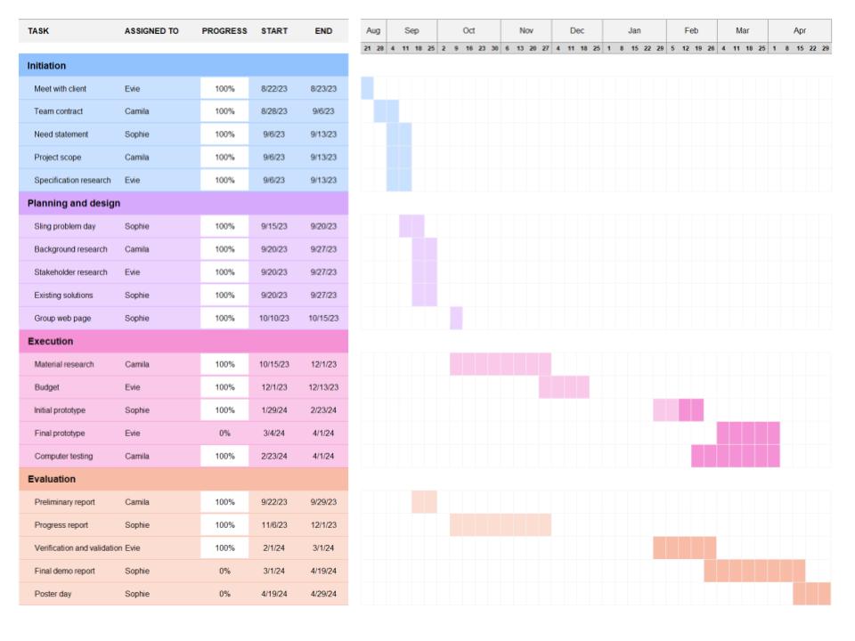
Figure A: Updated gantt chart and team responsibilities
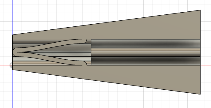
Figure B: Side view of updated CAD model showing updated spring design and shape. Springs have a more V-like shape with a more pointed tip. The springs are no longer of varying sizes, and the endplates are angled to account for the curvature of the L5-S1 region.
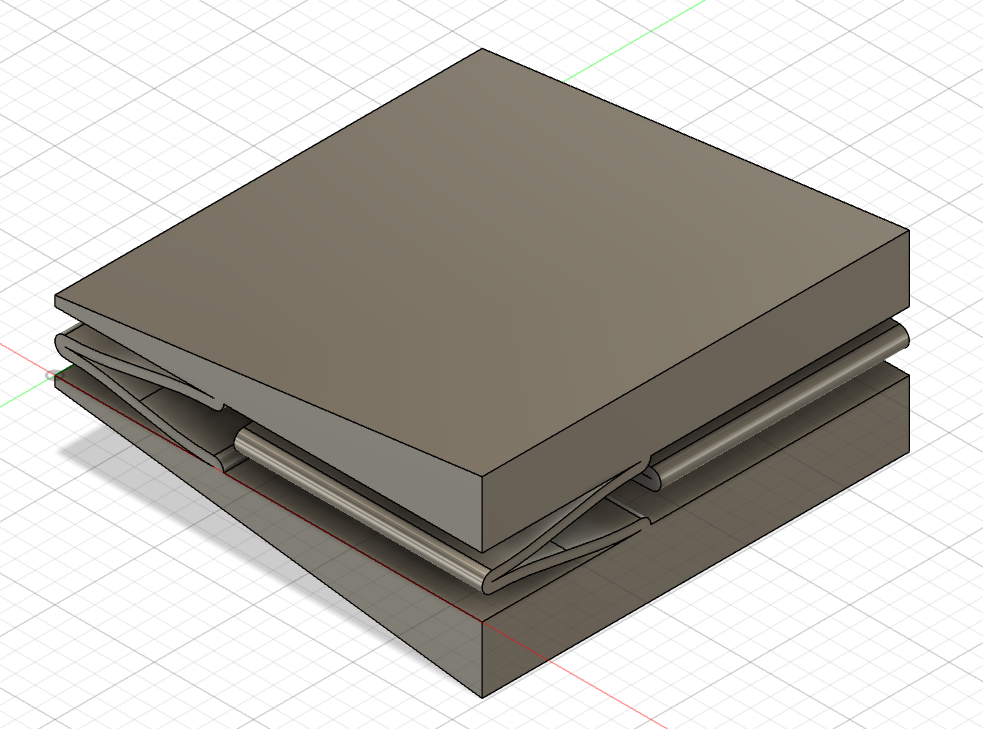
Figure C: Updated CAD model showing all design updates. The springs have a more V-like shape, as shown in Figure B, and they all have the same dimensions.
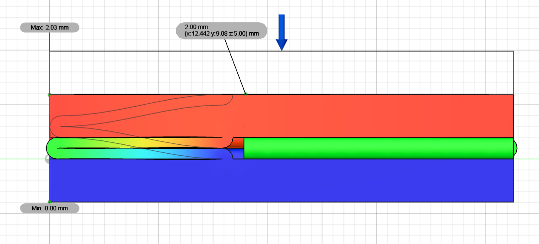
Figure D: Example of FEM testing on the final spring design with flat endplates.
Table A: Updated complete design specs and their corresponding verification testing
| Corresponding Paragraph | Design Specification | |
| Size | Thickness/Height | 6.1-10.3 ± 1.0 mm with an angle of curvature 15.3 ± 1.0 degrees [1] |
| Width | 55.3-58.6 ± 2.0 mm [39] | |
| Anteroposterior diameter | 15.5 ± 1.5 mm [40] | |
| Weight | Weight | 20 ± 5 g [4] |
| Compression | Sustain compression forces | Up to 300 N without functional failure [13] |
| Spring constant | Spring constant | 71.4 ± 2.0 N/m [14] |
| Shear | Resist shear forces | Up to 700 N in the anterior-posterior direction [41] |
| Torsion | Resist torsion forces | Up to 1200 N [42] |
| Degrees of freedom | Twisting during Flexion-Extension | 2.5 ± 2.1॰ [43] |
| Cephalad-Caudad Translation during Flexion-Extension | 1.0 ±1.3 mm [43] | |
| Bending during Flexion-Extension | 2.9 ±1.9॰ [43] | |
| Ease of surgery | Surgery requirement | Minimal trauma to adjacent vertebrae and discs, single procedure |
| Duration | Duration | > 13 years |
| Cost | Cost | < $10,000 |
| Attachment method | Plate adherence mechanics requirements, such as minimal slippage and compression and shear forces | |
| Biocompatibility | Biocompatibility in the L5-S1 spinal region | |
| MRI compatibility | Must be MRI compatible | |
Table B: Updated Budget Considerations including a 20% buffer for the PLA/PETG prints
| Vendor / location | Description | Cost | Quantity | Total Cost |
| 3D printing service (Protolabs) | 3D printed titanium implant | $500.00(includes fees & shipping) | 3 | $1500 |
| Makerspace | 3D printed PLA/PETG implant | $0.025 per gram($0.15 per piece) | 10 | $1.50 |
| Makerspace | 3D printed PLA/PETG L5-S1 vertebrae [44] | $0.025 per gram | 1 | $6.78 |
| $1508.28 |
Table C: FEM testing results including spring size, force applied, displacement, spring constant
| THICKNESS (mm) | LENGTH (mm) | WIDTH (mm) | FORCE APPLIED (N) | DISPLACEMENT (mm) | SPRING CONSTANT (N/m) |
| 0.5 | 9 | 10 | 800 | 1.673 | 478182.905 |
| 0.5 | 10 | 9.5 | 800 | 2.304 | 347222.2222 |
| 0.5 | 9 | 12 | 800 | 1.393 | 574300.0718 |
| 0.5 | 9 | 14 | 800 | 1.169 | 684345.5945 |
| 0.5 | 8 | 14 | 1200 | 1.102 | 1088929.22 |
| 0.5 | 8 | 13 | 1200 | 1.197 | 1002506.266 |
| 0.5 | 8.5 | 13.5 | 1200 | 1.507 | 796284.008 |
| 0.5 | 8.5 | 12.5 | 1200 | 1.662 | 722021.6606 |
| 0.5 | 8.5 | 12.5 | 1400 | 1.939 | 722021.6606 |
| 0.5 | 8.5 | 12.5 | 1444 | 2 | 722000 |
References
[1] Disc spaces, vertebral dimensions, and angle values at the lumbar region: a radioanatomical perspective in spines with L5–S1 transitions. Journal of Neurosurgery: Spine, 15(4), 2011.
[2] Passias, P. G., Wang, S., Kozanek, M., Xia, Q., Li, W., Grottkau, B., Wood, K. B., & Li, G. (2011). Segmental lumbar rotation in patients with discogenic low back pain during functional weight-bearing activities. The Journal of bone and joint surgery. American volume, 93(1), 29–37. https://doi.org/10.2106/JBJS.I.01348
[3] Xu, F., Zhou, S., Li, Z., Jiang, S., Chen, Z., Sun, Z., & Li, W. (2022). The 6 degrees-of-freedom range of motion of the L1–S1 vertebrae in young and middle-aged asymptomatic people. Frontiers in Surgery, 9. https://doi.org/10.3389/fsurg.2022.1002133
[4] Othman, Y. A., Verma, R., & Qureshi, S. A. (2019). Artificial disc replacement in spine surgery. Annals of translational medicine, 7(Suppl 5), S170. https://doi.org/10.21037/atm.2019.08.26.
[5] U.S. Food and Drug Administration. (n.d.). P170036B – Summary of Safety and Effectiveness Data (SSED). Retrieved from https://www.accessdata.fda.gov/cdrh_docs/pdf17/P170036B.pdf
[6] Techlab Systems. (2021). MTE 10-50 Universal Testing Machines – Technical Specification. Retrieved from https://techlabsystems.com/eng/wp-content/uploads/sites/2/2021/12/MTE_10-50_Universal_Testing_Machines-1-CAT-I-R9.pdf
[7] Umale, S., Yoganandan, N., & Kurpad, S. N. (2020). Development and validation of osteoligamentous lumbar spine under complex loading conditions: A step towards patient-specific modeling. Journal of the mechanical behavior of biomedical materials, 110, 103898. https://doi.org/10.1016/j.jmbbm.2020.103898
[8] BioPD. (n.d.). Torsion Testing. In BioPD. Retrieved from https://biopdi.com/torsion-testing/#:~:text=Here%E2%80%99s%20how%20a%20typical%20torsion%20test%20works%3A%201,while%20the%20other%20remains%20fixed.%20…%20More%20items
[9] ZwickRoell. (n.d.). Torsion Testers. Retrieved from https://www.zwickroell.com/products/static-materials-testing-machines/biaxial-and-triaxial-testing-machines/torsion-testers/
[10] ASTM International. (2020). ASTM F2423 – 11(2020)e1 Standard Guide for Functional, Kinematic, and Wear Assessment of Total Disc Prostheses (Standard No. F2423 – 11(2020)e1). Retrieved from https://www.astm.org/f2423-11r20.html
[11] Megad Danışmanlık. (n.d.). Bionix Spine Aşınma Simulator. Retrieved from https://megadanismanlik.com.tr/Upload/pdf/urun/Bionix%20Spine%20A%C5%9F%C4%B1nma%20Simulator.pdf
[12] ASTM International. (2019). ASTM F561 – 19 Standard Practice for Retrieval and Analysis of Medical Devices, and Associated Tissues and Fluids (Standard No. F561 – 19). Retrieved from https://www.astm.org/f0561-19.html
[13] U.S. Food and Drug Administration. (n.d.). P200022S003B – Summary of Safety and Effectiveness Data. Retrieved from https://www.accessdata.fda.gov/cdrh_docs/pdf20/P200022S003B.pdf
[14] KIRIYAMA, Y. (2003). SPIRAL – A New Concept in Spinal Force Measurement. Retrieved from https://isbweb.org/images/conf/2003/longAbstracts/KIRIYAMA_59-56_SPI_LONGE.pdf
[15] ADMET. (n.d.). EXPERT 5900 for Dynamic Orthopedic Testing. Retrieved from https://www.admet.com/testing-applications/materials/medical-devices-and-equipment-testing/expert-5900-for-dynamic-orthopedic-testing/
[16] Taguchi, T., & Lopez, M. J. (2021). An overview of de novo bone generation in animal models. Journal of orthopaedic research : official publication of the Orthopaedic Research Society, 39(1), 7–21. https://doi.org/10.1002/jor.24852
[17] Sidambe A. T. (2014). Biocompatibility of Advanced Manufactured Titanium Implants-A Review. Materials (Basel, Switzerland), 7(12), 8168–8188. https://doi.org/10.3390/ma7128168
[18] U.S. Food and Drug Administration. (2020). FDA Briefing Document Peripheral and Central Nervous System Drugs Advisory Committee Meeting. Retrieved from https://www.fda.gov/media/142959/download
[19] U.S. Food and Drug Administration. (2003). FDA Briefing Document Psychopharmacologic Drugs Advisory Committee Meeting. Retrieved from https://www.fda.gov/media/74201/download
[20] Lim, K. Z., Daly, C. D., Ghosh, P., Jenkin, G., Oehme, D., Cooper-White, J., Naidoo, T., & Goldschlager, T. (2017). Ovine Lumbar Intervertebral Disc Degeneration Model Utilizing a Lateral Retroperitoneal Drill Bit Injury. Journal of visualized experiments : JoVE, (123), 55753. https://doi.org/10.3791/55753
[21] Solveig M. Stubsjøen, Andreas S. Flø, Randi O. Moe, Andrew M. Janczak, Eystein Skjerve, Paul S. Valle, Adroaldo J. Zanella, Exploring non-invasive methods to assess pain in sheep, Physiology & Behavior, Volume 98, Issue 5, 2009, Pages 640-648, ISSN 0031-9384, https://doi.org/10.1016/j.physbeh.2009.09.019.
[22] Häger C., Biernot S., Buettner M., Glage S., Keubler L.M., Held N., Bleich E.M., Otto K., Müller C.W., Decker S., et al. The Sheep Grimace Scale as an indicator of post-operative distress and pain in laboratory sheep. PLoS ONE. 2017;12:e0175839. doi: 10.1371/journal.pone.0175839
[23] Susan J. Ley, Alex Livingston, Avril E. Waterman, The effect of chronic clinical pain on thermal and mechanical thresholds in sheep, Pain, Volume 39, Issue 3, 1989, Pages 353-357, ISSN 0304-3959, https://doi.org/10.1016/0304-3959(89)90049-3.
[24] Eckersall, P.D., Conner, J.G. Bovine and canine acute phase proteins. Veterinary Research Communications 12, 169–178 (1988). https://doi.org/10.1007/BF00362798
[25] Molony V, Kent JE, McKendrick IJ. Validation of a method for assessment of an acute pain in lambs. Appl Anim Behav Sci. 2002;76(3):215–238.
[26] Kim, J., & Breur, G. J. (2008). Temporospatial and kinetic characteristics of sheep walking on a pressure sensing walkway. Canadian journal of veterinary research = Revue canadienne de recherche veterinaire, 72(1), 50–55.
[27] Northern Sydney Local Health District. (n.d.). Guideline on Anaesthesia and Analgesia in Sheep. Retrieved from https://www.nslhd.health.nsw.gov.au/Research/ResearchOffice/Documents/ACEC_Guideline_Anaesthesia_Analgesia_Sheep.pdf
[28] Reddy, K. S., Naidu, M. U., Rani, P. U., & Rao, T. R. (2012). Human experimental pain models: A review of standardized methods in drug development. Journal of research in medical sciences : the official journal of Isfahan University of Medical Sciences, 17(6), 587–595.
[29] U.S. Food and Drug Administration. (n.d.). Medical Device Classification Database. Retrieved from https://www.accessdata.fda.gov/scripts/cdrh/cfdocs/cfPCD/classification.cfm?id=5026
[30] U.S. Food and Drug Administration. (n.d.). 21 CFR 860.3 – Definitions. Retrieved from https://www.accessdata.fda.gov/scripts/cdrh/cfdocs/cfcfr/cfrsearch.cfm?fr=860.3
[31] The FDA Group. (n.d.). PMA vs. 510(k): Understanding the Differences. The FDA Group Blog. Retrieved from https://www.thefdagroup.com/blog/pma-vs-510k
[32] U.S. Food and Drug Administration. (n.d.). IDE Application. Retrieved from https://www.fda.gov/medical-devices/investigational-device-exemption-ide/ide-application
[33] U.S. Food and Drug Administration. (2014). Draft Guidance for Industry and Food and Drug Administration Staff: The De Novo Classification Process (Evaluation of Automatic Class III Designation). Retrieved from https://www.fda.gov/media/141161/download
[34] U.S. Food and Drug Administration. (n.d.). TPLC Database Search. Retrieved from https://www.accessdata.fda.gov/scripts/cdrh/cfdocs/cfTPLC/tplc.cfm?id=5026
[35] Becker’s Spine Review. (n.d.). Lumbar disc replacement implant comparison: activL vs. ProDisc-L, Charite & 6 things to know. Becker’s Spine Review. Retrieved from https://www.beckersspine.com/spine/28662-lumbar-disc-replacement-implant-comparison-activl-vs-prodisc-l-charite-6-things-to-know.html
[36] Lu, S., Hai, Y., Kong, C., Wang, Q., Su, Q., Zang, L., Kang, N., Meng, X., & Wang, Y. (2015). An 11-year minimum follow-up of the Charite III lumbar disc replacement for the treatment of symptomatic degenerative disc disease. European Spine Journal, 24, 2056-2064. https://doi.org/10.1007/s00586-015-3939-5.
[37] Yale University. (Year). Yale Medicine Thesis Digital Library. EliScholar. Retrieved from https://elischolar.library.yale.edu/cgi/viewcontent.cgi?article=1443&context=ymtdl
[38] Yue, J., García, R., Blumenthal, S., Coric, D., Patel, V., Dinh, D., Buttermann, G., Deutsch, H., Miller, L., Persaud, E., & Ferko, N. (2019). Five-year Results of a Randomized Controlled Trial for Lumbar Artificial Discs in Single-level Degenerative Disc Disease.. Spine. https://doi.org/10.1097/BRS.0000000000003171.
[39] Lazennec, J. Y. (2020). Lumbar and cervical viscoelastic disc replacement: Concepts and current experience. World Journal of Orthopedics, 11(8), 345–356.
[40] Navid Arjmand, Mohammad Amini, Aboulfazl Shirazi-Adl, André Plamondon, Mohammad Parnianpour, Revised NIOSH Lifting Equation May generate spine loads exceeding recommended limits, International Journal of Industrial Ergonomics, Volume 47, 2015, Pages 1-8,ISSN 0169-8141, https://doi.org/10.1016/j.ergon.2014.09.010.
[41] Gallagher, S., & Marras, W. S. (2012). Tolerance of the lumbar spine to shear: a review and recommended exposure limits. Clinical biomechanics (Bristol, Avon), 27(10), 973–978. https://doi.org/10.1016/j.clinbiomech.2012.08.009.
[42] Umale, S., Yoganandan, N., & Kurpad, S. N. (2020). Development and validation of osteoligamentous lumbar spine under complex loading conditions: A step towards patient-specific modeling. Journal of the mechanical behavior of biomedical materials, 110, 103898. https://doi.org/10.1016/j.jmbbm.2020.103898
[43] Passias, P. G., Wang, S., Kozanek, M., Xia, Q., Li, W., Grottkau, B., Wood, K. B., & Li, G. (2011, January 5). Segmental lumbar rotation in patients with discogenic low back pain during functional weight-bearing activities. The Journal of bone and joint surgery. American volume. https://www.ncbi.nlm.nih.gov/pmc/articles/PMC3004094/
[44] embodi3d. (2015, October 22). Lumbar spine STL medical model. embodi3D.com. https://www.embodi3d.com/files/file/107-lumbar-spine-stl-medical-model/