Changes
Need Statement / Project Scope
The need statement and scope of the project has been revised in order to more adequately describe the problem and solution that is being presented. The project’s revised need statement is as follows: There is a need to develop a long-lasting disc replacement for the curved L5/S1 spinal region for patients experiencing a degenerative disc disease or injury, such as spondylolysis or a herniated disc, in order to relieve pain in the lumbar spine and restore movement and stability.
The project’s revised scope is as follows: Current solutions to disc disease and injury, specifically in the L5/S1 region have low patient satisfaction because they severely limit patient mobility and weight bearing abilities or cause the patient to endure other spinal complications. The disc replacement must ensure proper integration so the disc does not dislocate, sustains shear and translational forces further than compression, allows for natural range of motion including flexion and extension in the sagittal plane, lateral bending in the frontal plane, and rotation and compression in the axial plane [1], and is composed of a material that is biocompatible and possesses elastic resistance to optimally absorb a wide variety of shocks reverberating throughout the spine. A 3D printed model will be developed thereby serving as a physical prototype. Subsequently, the project plans to adhere to comprehensive evaluations of the prototype, utilizing both finite element analysis and modeling to ensure the integrity and functionality of the product. Important to note, forms of the prototype along with its subsequent iterations, will undergo rigorous physical examinations to assess its resilience against pertinent compressive, shear and translational forces. These assessments thereby aim to validate the capacity of the prototype in congruence to physiological specification, as well as refine the design for optimal performance. The designers/developers will complete a prototype of an artificial disc, slated for delivery on the final day of class, April 22nd of 2024.
Design Specifications and Team Responsibilities
Some of the design specifications have also been changed in accordance with the chosen solution. Table 1 contains the updated design specifications while the full table of specifications can be found in the Appendix. The six degrees of freedom and tri-planar motion was quantified by finding the amount of rotation that is considered a full range of motion. The thickness/height, width, and weight were generalized to fit a wider range that is representative of the average population. The average cost of a lumbar disc replacement implant in the United States is about $27,000 [2]. These products currently last about 10-13 years in the body should no complications arise [3]. Revive-L5’s client has specified that in order to break into the market and capture the necessary amount, the artificial disc replacement should cost less than $10,000 to produce, and should be able to last at least 13 years in the patient’s body. Lastly, based on conversations with surgeons, a surgery requirement was added to the design specification.
Table 1: Updated Design Specifications
| Thickness/Height | 6.1-10.3 ± 1.0 mm with an angle of curvature 15.3 ± 1.0 degrees [4] |
| Weight | 20 ± 5 g [5] |
| Width | 55.3-58.6 ± 2.0 mm [1] |
| Cost | < $10,000 |
| Surgery Requirement | Minimal trauma to adjacent vertebrae and discs, single procedure with |
| Duration | > 13 years |
| Twisting during Flexion-Extension | 2.5॰ ± 2.1 [6] |
| Cephalad-Caudad Translation (Vertical translation)during Flexion-Extension | 1.0 ± 1.3 mm [6] |
| Bending during Flexion-Extension | 2.9॰ ± 1.9 [6] |
The design schedule and team responsibilities have been updated to ensure that every milestone has a team member that is responsible for its completion. The updated Gantt chart can be found in the Appendix.
Statement of Design Alternative
When deciding on the final design, the client expressed the desire for the disc to follow a spring based design instead of the more traditional ball and socket approach. This desire is based on some success that the company had previously had in designing a disc replacement for the cervical spine. There were many design elements to be chosen like the shape of the springs as well as the quantity/configuration. After that a decision had to be made on the materials of the disc replacement as well as the method of attachment to the spine during surgery. A pugh chart as well as a written analysis are used to make all of these decisions.
Spring Shapes
The first thing to be decided is the shape of the springs in between the two endplates. The client wished for the artificial disc’s design to be a spring based system. As such, different spring shapes were theorized that would be optimal for the maximum amount of personnel and use cases. The first idea was that of a traditional spring that would attach to the insides of both endplates and coil around in the center as seen in Figure 1A. This shape would thereby allow for adequate compression of the plates in conjecture with one another and was an initial idea of what a spring loaded system looks like. The next idea as seen in Figure 1B, the V shape, is to centralize the load-bearing function of the spring in such a way that would alleviate stress on the end plates thereby preventing plastic deformation. Figure 1C, the X shape, was considered as an option for spring shape as it offers balanced support for both flexion-extension and lateral bending movements; both movements important within the L5-S1 region. Lastly Figure 1D, the U shape, was proposed to allow for an even distribution of forces along the entire surface of the end plate. Furthermore, this design allows for continual elastic deformation preventing plastic deformation and removes hard stop points allowing for flush compression against the endplates.

Figure 1: Spring shapes that were considered. A) Traditional spring. B) V shaped. C) X shaped. D) U shaped.
Spring Quantity/Configuration
Once the shape of the spring was decided, the next decision to be made was the quantity of springs as well as their configuration between the end plates. The first considered configuration is one large spring in the center, as shown in Figure 2A. The spring would be wide enough to span the baseplate, but attached in a single spot. This design was the baseline for the number and orientation of the springs due to the only one available orientation. The second considered configuration is two springs side-by-side and oriented in the same direction, as shown in Figure 2B. Since the disc has a relatively longer width as compared to the anterior-posterior (AP) diameter, it was theorized that two springs would allow for better force dissipation and would allow each spring to maintain elastic deformation better than a longer, single spring. The third considered configuration is two springs oriented in opposite directions with the endplate attachments in the center, as shown in Figure 2C. This design was proposed because while the angle of the L5-S1 region could make an asymmetrical design advantageous, having more symmetrical support could prevent overstressing one portion of the disc as force is applied fairly evenly. The fourth considered configuration is four springs rotated 90 degrees from each other in the clockwise direction, oriented such that the attachment points are along the perimeter, as shown in Figure 2D. Four springs were thought to be more advantageous than two because it would allow for better maintenance of the resting angle of the L5-S1 region. The attachment points being along the perimeter could be advantageous by preventing torsion and shifting, but this could also limit the angles to which the springs can be compressed. The fifth considered configuration is four springs rotated 90 degrees from each other in the counterclockwise direction, oriented such that the attachment points are in the center, as shown in Figure 2E. This design could have better force dissipation because there is more mass in the center, and it would ensure that the edges can be more compressed along various angles to provide a better range of motion.
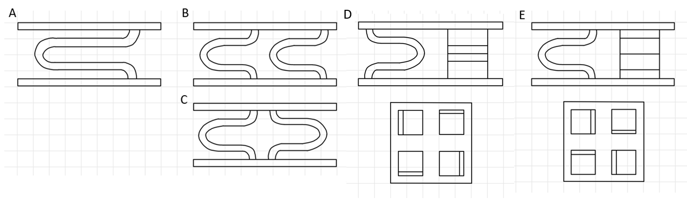
Figure 2: Spring quantities and configurations that were considered. A) Single spring. B) Two springs in the same direction. C) Two springs in opposite directions. D) Four springs attached along the perimeter. E) Four springs attached in the center.
Attachment Method
The next thing that needed to be decided was the method of attachment of the device onto the bone of the vertebrae. The first considered attachment method is three spikes grouped together on each end of the plate as shown in Figure 3A. This is a typical method used commonly in artificial disc replacements as it secures both ends of the plate and the connection points have a large contact surface area. The second considered attachment method is the same three spikes except spread out along the ends of the disc as shown in Figure 3B. This would provide the same contact area between the disc and the vertebrae, but would contain six different smaller connection points rather than two large ones. The third considered attachment method is a keel with spikes on top as shown in Figure 3C. Surgically, this entails an osteotomy, where the surgeon precisely incises into the vertebral bone to accommodate the insertion of the keel. This thereby enables the artificial disc to anchor centrally within the vertebral body rather than superficially attaching to the cortical surface. The last attachment method that was considered was a keel without the spikes as shown in Figure 3D. This was pioneered by the activ-L disc in order to improve mobility from the traditional spiked keel and to protrude less into the bone. While the spikes or keel provide a primary attachment method, there is a need for secondary attachment which is the bone growth into the material. Current research in orthopedic implant design suggests that end plates for spinal implants should be fabricated with a porous architecture. This design facilitates osseointegration, where new bone tissue grows into the porous structure of the implant over time. This thereby enhances the biomechanical stability and anchorage of the implant within the L5-S1 vertebrae in situ.

Figure 3: Attachment method ideas considered. A) Side spikes grouped. B) Side spikes spread out. C) Keel with spikes. D) Plain keel.
Material Choice
Another consideration for the design of this artificial disc replacement is what material to use. There exist only a handful of materials that can be used for implants but can also be 3D printed. The ones that were chosen to be compared were: UHMWPE, titanium and stainless steel. Ultra-High Molecular Weight Polyethylene (UHMWPE) was considered due to its high biocompatibility, shock adsorption and low wear properties especially under conditions of constant friction and mechanical stress. Titanium was a consideration as it is favorable for load-bearing applications due to its strength and lightweight nature. Furthermore, it has excellent corrosion resistance. Stainless steel was considered as it is a cost-effective option that provides robust mechanical support. In consideration of these materials, the combination of UHMWPE with either titanium or stainless steel was proposed. However, the use of multiple pieces would reduce the stability of the design and complicate the 3D printing process due to the difficulty of attaching the springs to the endplates post printing. Furthermore, these attachment points may represent potential loci of mechanical vulnerability upon application of force.
Analysis to determine solution
Spring Shapes
While considering the design for the artificial disc this region necessitates a unique motion range while balancing the ability to bear a variety of loads. The lumbar spine is subjected to a variety of lateral forces from movements such as twisting, bending and jumping. Thus, the spring component artificial disc especially in the context of athletes need to acknowledge these considerations to thereby prevent disc translation, ejection and/or adjacent segment disease. Essential to maintaining vertebral spacing is the ability of the spring to compress to the lowest possible thickness. Prevention of the vertebrae to fuse to adjacent segments greatly depends on the disc and specifically the spring’s ability to withstand plastic deformation. When projecting costs of the artificial disc, the amount of material needed is a primary consideration. With eventual plans to scale, the ease in the manufacturing process is practical to ensure consistent quality and scalability.
Table 2: Pugh Chart Considerations of Spring Design
| Possible Solutions | |||||
| Criteria | Weight | Loop | V | X | U |
| Adaptability to angle of L5-S1 disc | 10 | 1 | 8 | 6 | 10 |
| Resistance to torsion/ shifting | 9 | 3 | 7 | 10 | 7 |
| Contortion to minimum thickness | 8 | 4 | 5 | 2 | 10 |
| Plastic deformation | 7 | 2 | 10 | 8 | 4 |
| Amount of material | 3 | 6 | 10 | 4 | 9 |
| Ease of manufacturing | 4 | 5 | 9 | 8 | 10 |
| Total | 121 | 319 | 266 | 338 | |
Spring Quantity/Configuration
The quantity and configuration of the springs are vital to the effectiveness of the disc because they are the primary contributing factor to the maximum compression, torsion, and shear forces the disc can sustain, without causing injury or unnatural movement throughout the rest of the spine. The primary factor that was considered in regard to the number and positioning of springs is the adaptability to the angle of the L5-S1 disc. Since the L5-S1 disc must have a baseline angle of approximately 15.3 [4] degrees, there must be enough springs to hold the endplates along this angle. A singular spring will allow for significant movement, and will have a baseline angle of approximately 0 degrees, whereas four springs can have varying heights and contact enough of the perimeter to stabilize the endplates at a 15.3 degree angle. Two springs in the same direction can have different heights to somewhat stabilize the baseline angle, but two springs in opposite directions would be unlikely to maintain a baseline angle largely different from 0 because the attachment points are both in the center.
The next factor that was considered is the range of compression angles the springs can allow for in their orientations. With one spring, a compressive force heavily concentrated on one part of the disc would cause the disc to be tilted in that direction. Thus, the spring wouldn’t be able to dissipate the force throughout most of the disc. Four springs with the attachment points in the center would allow the endplates to tilt the small amount necessary to allow for spinal movement, while simultaneously restricting compressive forces from over-mobilizing the L5-S1 region.
While some torsion and shear is expected for mobility, excessive rotation and lateral shifting cause instability in the adjacent vertebrae. The most stable design will have the most support on the exterior, in order to restrict movement of the endplates. However, the four springs attached to the perimeter may over constrict the mobility of the region, making the four springs attached in the center more ideal.
Finally, the support distribution is the worst with only one spring because there is only one support feature between the endplates. The design with four springs in the center provides optimal support distribution because it can dissipate forces more evenly across the endplates and through the springs. The quantity of material utilized is inversely proportional to the number of springs incorporated into the design: a minimal number of springs results in the lowest amount of material used. Whereas an increase in the number of springs corresponds with a corresponding increase in material volume.
Table 3: Pugh Chart Considerations of Spring Quantity and Configurations
| Possible Solutions | ||||||
| Criteria | Weight | One | Two (same direction) | Two (opposite directions) | Four (perimeter) | Four (center) |
| Adaptability to angle of L5-S1 disc | 10 | 1 | 7 | 5 | 10 | 10 |
| Range of compression angles | 9 | 2 | 5 | 4 | 7 | 10 |
| Resistance to excessive torsion/ rotation | 8 | 1 | 3 | 5 | 9 | 10 |
| Resistance to excessive lateral shifting | 8 | 1 | 3 | 5 | 9 | 10 |
| Support distribution | 7 | 2 | 4 | 6 | 9 | 10 |
| Amount of material | 3 | 10 | 8 | 8 | 6 | 6 |
| Total | 88 | 215 | 232 | 388 | 438 | |
Attachment Method
A third pugh chart was made in order to evaluate the four attachment methods being considered. The most important criteria was ease of surgery as this feedback was the most consistent feedback received from interviewed surgeons. A keel requires that the surgeon performs an osteotomy, where the surgeons cut a groove into the bone to allow the keel to be fixated inside. With the spike method, this extra step can be eliminated from the surgery process. The next two criterias are reduced risk of complications should the device fail and that the vertebrae maintains its integrity after the surgery. Based on research, some current market designs with the keel fail after significant load bearing [7], because the bone began to crack above where it was excavated in order for the keel to fit. The group spikes run the risk of damaging the bone at the connection point due to an increase in contactable surface area in one location. The fourth criteria is that the attachment method is effective, which these all have been proved to be, with very few instances recorded of a disc detaching after surgery, especially with added security of the bone growth into the endplates. The fifth criteria is viability with adjacent injury. If multiple disc replacements are needed at once, the keel is not optimal because a vertebrae would need to be cut into on both the top and bottom. The last consideration is the attachment area which was characterized as the area being encompassed by all of the attachment points. The spread out spikes rank highest since there are six spread out attachment points and the keel ranks the lowest because there is only one point.
Table 4: Pugh Chart Considerations of Attachment Method
| Possible Solutions | |||||
| Criteria | Weight | Side Spikes (Spread Out) | Side Spikes (Grouped) | Keel W/ spikes | Keel |
| Ease of surgery | 10 | 8 | 10 | 3 | 3 |
| Reduced risk of complications upon failure | 9 | 10 | 9 | 6 | 7 |
| Vertebrae integrity after surgery | 8 | 10 | 10 | 2 | 2 |
| Effectiveness | 8 | 10 | 10 | 10 | 9 |
| Viability with adjacent injury | 7 | 10 | 10 | 4 | 5 |
| Attachment area | 6 | 10 | 8 | 7 | 6 |
| Total | 460 | 459 | 250 | 252 | |
Material Choice
A fourth pugh chart was constructed to assess materials based on critical parameters. The biocompatibility of the material was the primary consideration, since the materials should be nonreactive in order to ensure patient safety and implant longevity. Furthermore, the endurance of materials against degradation is essential to preserve both mechanical properties and functional efficacy. The material’s mechanical strength is also important as it needs to withstand both the tensile and compressive forces in the spinal column. The next consideration is the elasticity of spring and its ability to mimic the natural dynamics of the vertebral disc allowing adequate range of motion. The mass of the material is also critical as it needs to be sufficiently lightweight to alleviate stress on adjacent spinal structures, while simultaneously possessing the requisite durability to support the surrounding spinal integrity. Furthermore, the material’s capacity to facilitate osseointegration ensures the implant’s long-term anchorage and integration within the vertebral anatomy. Lastly, economic considerations of the cost of material are factored in hoping to strike a balance between cost efficiency to allow adequate accessibility.
Table 5: Pugh Chart Considerations of Material Choice
| Possible Solutions | ||||
| Criteria | Weight | Titanium [8,9] | Stainless Steel [8,9] | UHMWPE [10] |
| Biocompatibility | 10 | 10 | 6 | 8 |
| Material Degradation | 9 | 8 | 10 | 6 |
| Strength | 7 | 4 | 7 | 10 |
| Elasticity of spring | 9 | 7 | 1 | 6 |
| Weight | 8 | 7 | 2 | 5 |
| Endplate bone growth | 8 | 10 | 6 | 8 |
| Cost | 2 | 3 | 7 | 10 |
| Total | 405 | 286 | 382 | |
Chosen Solution
Based on the results of the pugh charts of the shape, quantity and configuration of the springs and then attachment method and materials a final design was constructed. The optimal design choice is four U shaped springs oriented in a circle. For the attachment style, because the spread out spikes and the group spikes are within a point of each other both will be prototyped so that proper mechanical testing can be completed. Since the spread out spikes technically had a higher score, that design will be tested first. The four U shaped springs in a circular configuration are optimal as they have a high adaptability to the angle of the L5-S1 region, have high support distribution and relatively high resistance to torsion. This allows for a higher range of motion relative to its other counterparts. The implant will be fully 3D printed out of titanium. The endplates will be printed with a porous design to allow for bone growth as a secondary fixation method. However, only the 90% of the endplate on the surface will be porous and the 10% that connects with the endplates will be solid in order to prevent bone growth into the spring that could affect its compression abilities. Figure 4 shows different views of the preliminary CAD models of the final design. The model is in its initial stage and will be modified to be the cult shape of the disk and then modified again after FEM testing in order to ensure that the design can withstand the necessary compression, shear, and torsion forces.

Figure 4: Initial CAD Model. A) Top right corner overhead view. B) Front side view. C) Right side view.
Budget
The prototype is estimated to cost $316.07 to 3D print in titanium. This number was obtained by uploading the STL File from the CAD model into Protoab [11]. The itemized budget is listed in Table 6. To ensure proper sizing, printing and resolution of the 3D printed titanium disc, part of the budget is allocated to making larger models of the designs and iterations out of PLA/PETG. This is also to test the attachment method and other variables in the designs. This will be done at the WashU Makerspace [12]. There is also allocation to print a to-scale model of the vertebrae and the actual L5/S1 disc space so that insertion can be tested and size can be confirmed [15]. Two titanium models will be printed after optimization and various forms of testing: one with the spike attachment method and one without. To facilitate proper compression testing without the necessity of constructing a specialized mount, this design ensures that the endplates can effectively press flat. This project will be funded using money from Sling Health. Sling funds each project $2000 so the design stays below budget since the total cost is $640.35.
Table 6: Rough Budget Considerations including a 20% buffer for the PLA/PETG prints
| Vendor / location | Description | Cost | Quantity | Total Cost |
| 3D printing service | 3D printed titanium implant | $316.07 | 2 | $632.07 |
| Makerspace | 3D printed PLA/PETG implant | $0.025 per gram($0.15 per piece) | 10 | $1.50 |
| Makerspace | 3D printed PLA/PETG L5-S1 vertebrae [15] | $0.025 per gram | 1 | $6.78 |
| $640.35 |
Appendix
Table A: Updated complete design specs
| Sustain shear forces | Up to 700 N in the anterior-posterior direction [13] |
| Sustain compression forces | – Up to 2000 N in the upright (0 degrees) position- Up to 3400 N for small trunk flexion angles (30 and 45 degrees) [14] |
| Thickness/Height | 6.1-10.3 ± 1.0 mm with an angle of curvature 15.3 ± 1.0 degrees |
| Anteroposterior diameter | 15.5 ± 1.5 mm [1] |
| Twisting during Flexion-Extension | 2.5 ± 2.1॰ |
| Cephalad-Caudad Translationduring Flexion-Extension | 1.0 ±1.3 mm |
| Bending during Flexion-Extension | 2.9 ±1.9॰ |
| Weight | 20 ± 5 g |
| Width | 55.3-58.6 ± 2.0 mm |
| Cost | < $10,000 |
| Surgery requirement | Minimal trauma to adjacent vertebrae and discs, single procedure |
| Duration | > 13 years |
| Plate adherence mechanics requirements, such as minimal slippage and compression and shear forces | |
| Biocompatibility in the L5-S1 spinal region. | |

Figure A: Updated gantt chart and team responsibilities
References
[1]Lazennec, J. Y. (2020). Lumbar and cervical viscoelastic disc replacement: Concepts and current experience. World Journal of Orthopedics, 11(8), 345–356.
[2]Lazennec, J. Y. (2020a, August 18). Lumbar and cervical viscoelastic disc replacement: Concepts and current experience. World Journal of Orthopedics.
[3] How long do artificial discs last. Spine Surgery. (n.d.). https://www.spine.md/artificial-disc-replacement/how-long-do-artificial-discs-last/
[4]Disc spaces, vertebral dimensions, and angle values at the lumbar region: a radioanatomical perspective in spines with L5–S1 transitions. Journal of Neurosurgery: Spine, 15(4), 2011.
[5] Othman, Y. A., Verma, R., & Qureshi, S. A. (2019). Artificial disc replacement in spine surgery. Annals of translational medicine, 7(Suppl 5), S170. https://doi.org/10.21037/atm.2019.08.26.
[6] Passias, P. G., Wang, S., Kozanek, M., Xia, Q., Li, W., Grottkau, B., Wood, K. B., & Li, G. (2011, January 5). Segmental lumbar rotation in patients with discogenic low back pain during functional weight-bearing activities. The Journal of bone and joint surgery. American volume. https://www.ncbi.nlm.nih.gov/pmc/articles/PMC3004094/
[7] Reeks, J., & Liang, H. (2015, April 28). Materials and their failure mechanisms in total disc replacement. MDPI. https://www.mdpi.com/2075-4442/3/2/346
[8] Sahoo, N. K., Anand, S. C., Bhardwaj, J. R., Sachdeva, V. P., & Sapru, B. L. (1994, January). Bone response to stainless steel and titanium bone plates: An experimental study on animals. Medical journal, Armed Forces India. https://www.ncbi.nlm.nih.gov/pmc/articles/PMC5529616/
[9]Aesteiron. (n.d.). Stainless Steel vs titanium. https://www.aesteiron.com/blog/stainless-steel-vs-titanium.html
[10] Hussain, M., Naqvi, R. A., Abbas, N., Khan, S. M., Nawaz, S., Hussain, A., Zahra, N., & Khalid, M. W. (2020, February 4). Ultra-high-molecular-weight-polyethylene (UHMWPE) as a promising polymer material for biomedical applications: A concise review. Polymers. https://www.ncbi.nlm.nih.gov/pmc/articles/PMC7077409/#:~:text=Ultra%2DHigh%20Molecular%20Weight%20Polyethylene%20(UHMWPE)%20is%20an%20engineering,average%20chain%20length%20%5B1%5D
[11] Rapid prototyping & on-demand production services. Protolabs. (n.d.). https://www.protolabs.com/
[12] Spartan Light Metal Products Makerspace. (n.d.). https://jubelmakerspace.wustl.edu/faq/#HowdoIsubmita3Dprintjob. Jubel Makerspace FAQ.
[13] Gallagher, S., & Marras, W. S. (2012). Tolerance of the lumbar spine to shear: a review and recommended exposure limits. Clinical biomechanics (Bristol, Avon), 27(10), 973–978. https://doi.org/10.1016/j.clinbiomech.2012.08.009.
[14] Navid Arjmand, Mohammad Amini, Aboulfazl Shirazi-Adl, André Plamondon, Mohammad Parnianpour, Revised NIOSH Lifting Equation May generate spine loads exceeding recommended limits, International Journal of Industrial Ergonomics, Volume 47, 2015, Pages 1-8,ISSN 0169-8141, https://doi.org/10.1016/j.ergon.2014.09.010.
[15] embodi3d. (2015, October 22). Lumbar spine STL medical model. embodi3D.com. https://www.embodi3d.com/files/file/107-lumbar-spine-stl-medical-model/