The Microball consists of 95 CsI(Tl) scintillators closely packed to cover the angular range 4.0o – 172o. The detectors are arranged in 9 rings with increasing forward segmentation. The device is optimally designed to be used in conjunction with Gammasphere. The scintillator light is collected by silicon photodiodes that provide high quantum efficiency and minimal mass. The signals are processed through a charge sensitive preamplifier followed by a slow shaper. Particle identification for 1,2,3H, 3,4He, Li, Be and B ions is accomplished by pulse shape discrimination.
Characteristics of the Microball
The features of the Microball are summarized below:
- Good charged-particle identification (PID). Each detector of the device provides charged-particle identification, which is essential for selecting reaction channels.
- Large solid angle coverage (~97% of 4p ). This becomes very important when a weak channel such as (HI, p2n) needs to be selected in the presence of much stronger channels such as (HI,3p). This large coverage was achieved geometrically, but other factors may reduce the actual detection efficiency. For forward angles excellent particle identification is achieved. However, at large angles for symmetric reactions and/or lighter compound systems the lowest energy alpha particles and protons are not be completely distinguished, and this decreases somewhat the identification efficiency. The importance of large efficiency is apparent, for example, when channels like (HI, 3p) or (HI,4p) need to be measured.
- Small total mass. This requirement is essential to minimize degradation of the peak to total ratio of the Gammasphere Ge detectors. It is imperative for spectroscopic studies, but not as crucial for reaction mechanism studies.
- Adequate segmentation. This allows for nearly equally the counting rate among the detectors for many reaction asymmetries in the entrance channel. It helps keeping up with the high event rates of Gammasphere. Decreasing the solid angle of each detector with decreasing angle relative to the beam allows angular distributions of light charged particles to be measured with nearly equal statistical quality for all angles.
- Reasonably good energy resolution. This requirement permits measurement of particle evaporation spectra with good energy definition below and above the emission barrier.
- Excellent gain stability with counting rate, temperature and time. This is very important for obtaining good quality data. Often counting rate dependent shifts may not be possible to correct in the offline analysis, or it may require very time consuming gain shift corrections in order to retain the PID.
- The device is small enough to fit inside the Gammasphere scattering chamber
The Geometric Parameters of the Microball
The parameters of the Microball are summarized in Table 1.1. The number of the detectors and their distance from the target in each ring are given in the second and third rows, respectively. The fourth and fifth rows give the polar angles, q, at the center of each ring and the corresponding half angle. A spherical polar coordinate system is used with the beam along the z axis. The azimuthal angle f = 0 is at the top and increases clockwise when going with the beam. Columns six and seven give the solid angle for one detector at each ring in milli-steradians and the normalized solid angle relative to a detector in the first ring. The next column gives the light guide thickness in mm. The last 6 rows give the average CsI(Tl) thicknesses in each ring for the two devices, as well as the maximum energies of protons and alpha particles that stop in the detectors.

Read More about the Microball
The details of the design and the performance characteristics of the Microball are available in a publication in Nuclear Instruments and Methods, A381, 418 (1996). For reprints in color contact D.G. Sarantites at dgs@wustl.edu.
To read a PDF file (3.0 MB) of the Microball NIM paper click here Microball-NIM. To see the Microball Pictures in color just go to Microball Images in the Front Page or look at some of them just above in this page.
There is also a NIM paper describing simulations of the Gammasphere performance through the Microball. There you will also find what the (H,k) response of the Gammasphere is with or without the Hevimet Shields in place. For the simulations paper (780 kB) click here Gammasphere Simulations NIM paper.
The Spectroscopy Microball-A (the thin one)
The Microball had its maiden set of experiments in March 1994 with the early implementation of Gammasphere. In order to make these experiments possible a special acquisition system based on the MSU 4p acquisition was implemented, thanks to Skip Vanden Mollen, in order to allow a rapid FERA ECL bus readout.
The first three experiments performed with the Microball were:
- (MB-1) 230 MeV 51V + 100Mo
- (MB-2) 130 MeV 29Si + 58Ni
- (MB-3) 135 MeV 32S + 58Ni
with 36 Ge detectors in Gammasphere.
In those experiments the detectors of the Microball were wrapped with 0.290 mg/cm2 aluminized Mylar and protective absorbers of Pb and Sn60/Pb40 were used.
The beam currents employed in these experiments were typically 3 pnA on about 0.3 mg/cm2 targets. The linear amplifier shaping constants were adjusted to have peaking times at 4.5 microseconds with the energy and PID gates at 4.0 and 14.0 microseconds (gate widths 1.2 and 0.050 microseconds), respectively. In all these cases a common E and a PID gate (early and late) was applied to all 96 channels of FERA ADCs. Under these conditions, the rates per detector were approximately 2,000 c/s for Experiment 1 and 3,000 c/s for Experiments 2 and 3. The pileup rates were typically 1-3% depending on experiment and detector angle and rate.
The proton detection efficiency for Exp. 1 was measured to be 0.89.
The early reports from this work is given in the references below.
Experiments in 1995 – Final Gammasphere Configuration
The second set of experiments of the Microball with Gammasphere had to wait nearly 14 months for the completion of the VXI interface module that permits readout of the external FERA ADC’s. The following experiments were performed in July and August of 1995.
- (MB-4) 230 MeV 51V + 100Mo
- (MB-5) 130 MeV 28Si + 58Ni
- (MB-6) 150 MeV 48Ca + 100Mo
- (MB-7) 150 MeV 27Al + 132Te
- (MB-8) 180 MeV 35Cl + 105Pd
- (MB-9) 230 MeV 51V + 98Mo
In this round of experiments the Gammasphere had 57 Ge detectors. Encouraged by the previous success, we wanted to increase the counting rates in the Microball and at the same time retain the small pile up rates that we had before.
The improvement to the Microball signal processing was to shorten the time constants in all the 96 shapers to a peaking time of 3.2 microseconds. This allowed the PID gate to be moved to 9.0 microseconds. In this way the counting rates could be increased to about 4,000 c/s per detector, while the beam currents were increased to 4-6 pnA. As before a common E and a PID gate was employed for all 96 detectors.
Although the particle identification resolution was nearly as good as in Experiments 1-3, with the increased beam intensity, we experienced a major difficulty due to periodic sparking and base line deterioration after the linear shapers and base line restorers. This was associated with the increased beam intensities. Interestingly, we found that about 300 nA of negative current (due to electrons from atomic collisions of the beam with the target) was hitting any one of the detectors. A temporary solution was implemented by grounding each ring of the Microball detectors to the chamber with Al foil.
Here a new technique for PID was employed. This time it was possible to store the cyclotron RF and thus use it as a time reference for the Microball constant fraction signals. These times provide an additional method for doing the particle identification. Thus the new feature is that we can use for the pulse shape (early to late ratio) and the crossing time and get a dual identification procedure. It was thus found that for the detectors for which the sparking was absent the ratio method gave superior PID resolution. When the sparking affected the base line, then the crossing time provided better PID resolution which was just adequate to separate protons and alphas.
The proton detection efficiency for experiments 4 and 5 was measured after the experiments were completed and found to be 0.78-0.83. This was disturbingly low and its origin was not understood until a year later (see following section).
Another difficulty associated with the on line monitoring of the performance of the Microball was the presence of two misplaced groups of particles in the E vs. PID maps that appeared to have the wrong timing relative to the prompt coincidences. Most of these could be rejected in the off-line analysis, but again their origin was not clearly identified until the next set of experiments were carried out.
Early reports from these experiments have been presented in the Gammasphere dedication conference and at the Argonne International Conference.
Experiments in 1997
Prior to the next set of experiments some of the Microball Sn absorbers were replaced with equal thickness of SnPb ones and the Microball was tested for reliable performance at Washington University.
In January and February 1997 nine (9) additional experiments were performed:
- (MB-21, GS-87) Light output measurements of the Microball detectors using Elab/A = 12.0, 10.0, 8.0, 6.1 MeV protons and alpha particles on 232Th (, D.G. Sarantites et al. ).
- (MB-22, GS-88) 250 MeV 58Ni + 50Cr (Microball, Neutron det. and Gammasphere, S. Freeman et al.).
- (MB-23, GS-89) 250 MeV 58Ni + 58Ni (Microball, Neutron det. and Gammasphere, J. Smith et al.).
- (MB-24, GS-90) 125 MeV 28Si + 40Ca (Microball, Neutron det. and Gammasphere, C. Baktash et al. ).
- (MB-26, GS-91) 157 MeV 48Ca + 26Mg (Microball and Gammasphere, M. Devlin et al.).
- (MB-27, GS-92) 135 MeV 32S + 58Ni on Ta (Microball and Gammasphere, S. Tabor et al.).
- (MB-28, GS-93) 310 MeV 76Ge + 96Zr (Microball and Gammasphere, B. Herskind/I.Y. Lee, et al.).
- (MB-29, GS-94) 350 MeV 78Kr + 103Rh (Microball and Gammasphere, M. Carpenter et al.).
- (MB-30, GS-95) 173 MeV 35Cl + 105Pd on Au (Microball and Gammasphere, M. Riley et al. ).
Here you can find the Parameters for experiments MB-21 through MB-30 or GS-87 through GS-95.
During the group of experiments (GS-87 through GS-95) the detector No 17 (in bank 2-0) was functioning intermittently (most of the time it was Ok). The problem was an internal connection that was fixed only at the end of the runs.
In the interval between runs a new preamplifier power box was completed and is currently being tested. It is more modular and much more convenient if repairs are needed. It will be used in the next set of experiments.
We have also made external attenuators that conveniently allow changing the time range of the CsI FTCs. We are planning to extend the range to cover 1 ms, which matches the time range of the Ge detectors.
The last group of approved experiments, while Gammasphere was still at LBNL, were carried out in May and June 1997. For these experiments, the Microball absorbers for the first few front rings were changed and made thinner.
These experiments were:
- (MB-31, GS-108) 230 MeV 60Ni + 100Mo (X-ray Detectors, Microball and Gammasphere , L.G. Sobotka et al.).
- (MB-32, GS-109) 160 MeV 40Ca + 58Ni (Microball and Gammasphere, A.O. Macchiavelli et al.).
- (MB-33, GS-110) 130 MeV 28Si + 58Ni(Au) (Microball and Gammasphere, D.R. LaFosse, F. Lerma et al.).
- (MB-34, GS-111), 130 MeV 29Si + 58Ni(Au) (Microball and Gammasphere, D.R. LaFosse, F. Lerma et al.).
- (MB-35, GS-112) 128 MeV 29Si + 40Ca (Microball and Gammasphere, C. Baktash et al.).
They were all quite successful. You can find the Microball parameters for the above group of experiments here: Parameters for experiments MB-31 through MB-35 or GS-108 through GS-112.
Experiments in 1998
First group at ATLAS ( Feb. 24 – March 13, 1998)
Now the Gammasphere is at ATLAS at the Argonne National Laboratory. The Microball was installed in the Gammasphere on the 14th of February. New procedures for aligning it in its chamber and in front of the FMA had to be devised. The ribbon cables for the Microball signals were strung by the Washington University personnel. There were the usual problems with CAMAC crates and failing FERA ADC’s. Finally these were solved and the first group of experiments at ATLAS with the Gammasphere having 100 Ge detectors installed, the Microball and the FMA began.
The ANL personnel are thanked for the superb assistance and willingness to help the users. The Gammasphere operation still has some rough spots due to to trip from LBNL, but it is getting there. For example: what happened to the Ge detector absorbers (Ta + Cu)., why are the EFFs crush every 20 – 120 minutes, why are the tape routers and distributors not functioning for all EFFs? The EFF problem seems to have been fixed , Thanks to Torben. The Tapers are not totally out of the woods yet.
Anyway, the first round of Microball experiments were completed and the Microball is safe at home. The experiments completed are:
- (MB-36, GSFMA-6A) 260 MeV 64Zn + 64Zn, (Gammasphere, Microball, FMA, PPAC, Ionization chamber; J. Smith et al.).
- (MB-37, GSFMA-6B) 265 MeV 64Zn + 58Ni, (Gammasphere, Microball, FMA, PPAC, Ionization chamber; J. Smith et al.).
- (MB-38, GSFMA-7,) 12-48 MeV 4He + 232Th, (Microball standalone; D.G. Sarantites et al.)
- (MB-39, GSFMA-8) 84 MeV 20Ne + 28Si, (Gammasphere, Microball, FMA, Channel plates (one only), Ionization chamber; D.G. Sarantites, J. Wilson et al.).
- (MB-40, GSFMA-9) 135 MeV 32S + 40Ca, (Gammasphere, Microball, FMA, Channel plates (one only), Ionization chamber; C. Svensson et al.).
The Microball parameters for this group of experiments can be found here: Parameters for experiments MB-36 through M-40 or GSFMA-6A through GSFMA-9. The results of the Microball calibration for the above experiments are available here Microballcalibration from MB-38. For further information ask here dgs@wustl.edu.
Experiments in June 1998 (ATLAS)
The Microball was set up in June 4 for the next three approved experiments at ATLAS. As usual, all 95 of the 95 Microball detectors are working. More important, however, is that all 18 of the FERA ADCs are by “magic” now operating in one CAMAC crate, as they always did at LBNL!!
These three completed experiments and calibration are:
- (MB-41, GSFMA-19) 160 MeV 40Ca + 40Ca (Microball + Neutrons + FMA with PPAC + I.C. and Gammasphere, D. Balamuth, et al.).
- (MB-42, GSFMA-20) 11.96 MeV 1H + 12C. (Microball self triggered for energy calibration of this group of experiments. Please contact DGS below for details, Completed and analyzed (see table below).
- (MB-43, GSFMA-21) 238 MeV 58Ni + 54Fe (Microball + FMA with PPAC, DSSD and Gammasphere, R.M. Clark, et al.).
- (MB-44, GSFMA-22) 184 MeV 40Ca + 92Mo (Microball + FMA + PPAC and Gammasphere, L.L. Riedinger, et al.).
For the good news read below.
Prior to experiment MB-41, the Microball base lines for all banks were adjusted to ~ -(1.5±0.5) mV. Then the pedestals were measured by downloading 0 for each channel and then measuring the all simultaneously. The acquisition did not crash!!! Thanks Torben, keep up the good work. The pedestals were calculated with LaFosse’s little program and then checked. Great job. Interestingly, the pedestals for the PID (tail) was also sharp, indicating good baseline stability. This was indeed seen in experiment MB-41 where, for the first time, the noise level at the back detectors was at the same level as the front ones (3-5 mV, RMS values). What happened to the electron noise that plagued MB-36 and many other runs ???
The Microball parameters for this group of experiments is the same as for the MB-36 through MB-40. Here are the current Parameters for experiments MB-41, MB-42, MB-43 and MB-44. The a-particle calibration of the Microball for the above experiments and all future ones is available here: Microball Alpha calibration coefficients for all future experiments. Only the alpha coefficients are given for this group of experiments. The proton energies that are needed were determined in experiment MB-42. The data were analyzed by J.W. The proton energy calibration coefficients were calculated by DGS and are given here: Proton coefficients file. The slopes and intercepts in MeV/channel (2048 full scale) and MeV, respectively, are tabulated. For your proton energies use these. For the alphas, get the proton energy in MeV and insert it in the expression(s) for the non-linear alpha response given above.
For the 40Ca + 92Mo run we had 7-8 pnA of beam on a 0.7 mg/cm2 target. The front Ge were counting at 9-10 kHz, while the Microball operated at 4200 c/s per detector with excellent resolution for alphas and protons.
The proton efficiency of the Microball for MB-43 was measured to be 88%, while that for alphas was 72%. Higher efficiencies, particularly for a’s, should be obtained for MB-44. In that run a 3-pnA of 58Ni beam was used which was focussed through a 2 mm aperture to 1 mm diameter. It was burning a hole in the 0.54 mg/cm254Fe target!
The Microball is now (July 2, 1998) back home.
Experiments in November 1998 (ATLAS)
On November 2 the Microball was setup again at ATLAS in Gammasphere for the next group of four experiments. One bad cable was identified for detector 2-00. That detector was connected to the spare cable (Target position) as detector 62 instead of 17. The detector in Bank 1-6 is flaky and noisy.
The new experiments are:
- (MB-45, GSFMA-39) 257 MeV 60Ni + 50Cr (Microball + Neutrons + FMA with Channel plates + I.C. and Gammasphere, S. Freeman, et al.). Completed.
- (MB-46,GSFMA-40) 185 MeV 40Ca + 58Ni (Microball + Neutrons + FMA with Channel plates + I.C. and Gammasphere, B. Cederwall, et al. ). It ran for less than a day and then cancelled due to Gammasphere acquisistion failure. It will be rescheduled later.
- (MB-47,GSFMA-41) 215 MeV 58Ni + 46Ti (Microball + Neutrons + FMA with Channel plates + I.C. and Gammasphere, R. Clark, et al.). Completed succesfully.
- (MB-47A,GSFMA-41A) 12 MeV p + 12C (Microball stand-alone, Washington U. group).
- (MB-48,GSFMA-42) 141 MeV 36Ar + 28Si (Silicon Microstrip Wall, Microball, Neutron detectors, Gammasphere and No FMA, D. Rudolph et al.). Completed succesfully.
- (MB-48A,GSFMA-42A) 12 MeV p + 12C (Si Microstrip Wall and Microball, stand-alone, Washington U. group). Completed succesfully. The calibration of the Si Wall with protons worked very well. The alpha calibration of the DE detectors showed superb energy resolution (better than 40 keV FWHM at 5.8 MeV).
The Threshold and Gain Files that are used in the Microball Control Panel in the IBM PC that controls the Microball for this group of experiments are: MB-45.dat through MB-48.dat, respectively.
The parameter file for the above experiments can be found here: Parameters for experiments MB-45 to MB-47 , or GSFMA-39 to GSFMA-42. The calibration coefficients from the MB-47A experiment that apply to MB-45, MB-46 and MB-47 are available here : Proton coefficients file. In this file the slopes and intercepts in MeV/channel (2048 full scale) and MeV, respectively, are tabulated. For your proton energies use these. The proton coefficients for MB-48A will become available shortly, please, be patient.
The parameter file for the Microball for experiment MB-48 is the same as the MB-47 but with the first 28 CsI detectors removed and the target position empty in detector 62.
Important Extra Help from the Washington U. group: The alpha calibration now is at hand. So from the proton coefficients it is possible to calculate externally all the particle relevant quantities for each experiment. DGS wrote a program to compute the following quantities for each type of particle (protons and alphas) and each detector as a function of the raw channel number (0 to 2047) :
- The Center-of-Mass Angle
- The Center-of-Mass Energy
- The Laboratory Frame Energy
- The Jacobian (sC.M./sLab).
Eight files can be made available containing the above quantities, 4 for protons and 4 for alpha particles.
So for a given channel number for a proton or an alpha, the above quantities are available in table look-up form. Thus, the lab energy calibrations of the CsI, the multilayer absorber corrections, and CoM conversions for your reaction will all be included. Please send email to DGS to obtain these files. You may request these setup files for the MB-46 and MB-47 experiments by contacting Demetrios Sarantites at Please have the reaction, the target thickness and orientation, and the beam energy at mid-target available when you inquire.
This is guaranteed to save you a lot of time in your data analysis.
You may request these setup files for the MB-46 and MB-47 experiments by contacting Demetrios Sarantites at dgs@wustl.edu.
The setup files needed for these calculations are there also for your information. Enjoy.
For further information ask : dgs@wustl.edu
Experiments in July 6 1999 (ATLAS)
On July 6, 1999 the Microball was setup again at ATLAS in Gammasphere for yet another group of four experiments. One bad cable was identified for detector 1-13 (or det 14). Experiment MB-49 is done with that detector missing.
- (MB-49, GSFMA-64) 75 MeV 16O + 24Mg (Microball and Gammasphere, No FMA, C.Baktash, A. Macchiavelli, and D.G. Sarantites, et al.).
- (MB-50, GSFMA-65) 165 MeV 48Ca + 30Si (Microball and Gammasphere, No FMA, M. Devlin, et al.).
- (MB-50A, GSFMA-65A) 12 MeV protons on 12C (Microball standalone calibration; D.G. Sarantites et al.).
- (MB-51, GSFMA-66) 122 MeV 28Si + 40Ca (Microball and Gammasphere, No FMA, C. Svensson, et al.)
- (MB-52, GSFMA-67) 180 MeV 40Ca + 94Mo (Microball and Gammasphere, No FMA, D. Hartley et al.)
All 4 experiments above were done succesfully.
Parameters for experiments MB-49 and MB-50 here the cables for banks 5 and 6 were switched by mistake during setup and were left switched. We did not find out about this until the proton calibration did not make sense. Elastic scattering at 170 degrees still works!
Parameters for experiments MB-51 and MB-52.
The Microball calibration files for MB-49 (GSFMA64), MB-50 (GSFMA65), MB-51(GSFMA66) and MB-52(GSFMA67) are ready. They contain the following information for both protons and alphas:
- The Center-of-Mass Angle
- The Center-of-Mass Energy
- The Laboratory Frame Energy
- The Jacobian (sC.M./sLab).
Eight files are available containing the above quantities, 4 for protons and 4 for alpha particles.
So for a given channel number for a proton or an alpha, the above quantities are available in table look-up form. For a given channel number of the particle of interest simply look up the appropriate quantity in the proper table. The laboratory frame energy calibrations of the CsI, the multilayer absorber corrections, and CoM conversions for your reaction are all be included.
This is guaranteed to save you a lot of time in your data analysis.
You may find (download) these files for the MB- 49 (GSFMA64), MB-50 (GSFMA65), MB-51 (GSFMA66), and MB-51(GSFMA67) experiments by requesting them from Demetrios Sarantites: dgs@wustl.edu.
The Calibration files for these experiments (MB-49, MB-50, and MB-51) are available from dgs on request. Please send email for instructions to: dgs@wustl.edu
Experiments in September 27, 1999 (ATLAS)
On September 24, the Microball and the Neutron Shell were installed in Gammasphere for another group of 8 experiments. For the Neutron Shell these were the first experiments.
In this setup detector 15 is missing (broken cable again) and detector 17 was moved to the target position 62.
The first group of experiments performed with the Neutron Shell and the Microball was:
- (MB-53, NS-1, GSFMA-73) 130 MeV 32S + 28Si (Gammasphere, Neutron shell, Microball, D.G. Sarantites et al.) Completed succesfully.
- (MB-54, NS-2, GSFMA-74) 100 MeV 32S + 40Ca (Gammasphere, Neutron shell, Microball, FMA) P. Fallon et al. Completed succesfully.
- (MB-55, NS-3, GSFMA-74) 145 MeV 36Ar + 40Ca (Gammasphere, Microball, Neutron shell, FMA) P.Fallon et al. Completed succesfully.
- (MB-56, GSFMA-75) 12 MeV p + 12C (Microball, stand- alone, Washington U. group).
- (MB-57, NS-4, GSFMA-76) 185 MeV 40Ca + 58Ni, Gammasphere, Microball, Neutron Shell, FMA, B. Cederwall et al. Completed succesfully.
- (MB-58, NS-5, GSFMA-77) 125 MeV 40Ca + 40Ca, Gammasphere, Microball, Neutron Shell, S. Paul et al.. Postponed (operations lost the Ca in the source.)
- (MB-59, NS-6, GSFMA-78)Beam 225 MeV 58Ni + 50Cr, Gammasphere, Microball, Neutron Shell, no FMA, C. Baktash et al. Completed succesfully.
- (MB-58A, NS-5A, GSFMA-77) 125 MeV 40Ca + 40Ca, Gammasphere, Microball, Neutron Shell, no FMA, S. Paul et al. Repeated and done succesfully.
- (MB-59, NS-7, GSFMA-79) 260 MeV 64Zn + 64Zn, Gammasphere, Microball, Neutron Shell, and FMA, D. LaFosse et al.. Completed succesfully.
- (MB-60, GSFMA-80) 235 MeV 58Ni + 58Ni, D. Seweryniak et al.(Microball, Neutron Shell, Si detectors) Succesfully attempted.
- (MB-61, GSFMA-81) 12 MeV p + 12C (Microball, stand- alone, Washington U. group). Completed
- (MB-62, GSFMA-82) 207 MeV 54Fe + 58Ni, D. G. Sarantites et al.(Microball, Neutron Shell, Si cube) Completed. Lots of accelerator trouble, lost quite a bit of beam time (not recovered).
This marks the first and last Microball + Neutron shell experiments with Gammasphere at ATLAS.
The Neutron detector gain matching was done approximately with the 2615 keV gamma from a 228Th source. The edge of that gamma was placed at approximately channel 1900 in the high gain energy spectra. It corresponds to about 6 MeV in neutron energy.
The setup had 78 Ge detectors in Gammasphere, 30 Neutron detectors and 94 out of 95 working detectors in the Microball. In experiment MB-56 the detector 14 fixed “itself”. From then on all 95 out 95 detectors in the Microball work.
Parameters for experiments MB-53 to MB-60, or GSFMA-73 to GSFMA-79 . Parameters for experiment MB-62, or GSFMA-83 Since the rings 2 and 4 of the Microball were removed and the rings 1 and 3 were moved back to make room for the Si cube, the angles for the detectors in rings 1 and 3 must be recalculated.
The configuration file for the Neutron Shell contains angles and positions of the neutron detectors in Gammasphere. Configuration file for the Neutron Shell.
Microball Calibration files for the MB-53 (GSFMA73), MB-54, MB-55, and MB-57 (GSFMA76) experiments are available by request to DGS by sending email to dgs@wustl.edu.
Experiments in February 3, 2000 (Last group at ATLAS)
The last two Microball + Gammasphere experiments at ATLAS began on February 3, 2000. In about five weeks from the begining of these experments Gammasphere will be dismantled and moved back to LBNL where it will resume operation. The Miocroball will be available for experiments at LBNL at that time.
Since the previous group of experiments, the Microball underwent a small but probably important improvement. The RTV potting of the cables inside the chamber was removed and modified. The 34 pin connectors have now been encased in Al housings that support the PC 50-Ohm boards better. This will reduce the breakage of the thin cables from handling them during assembly. A better grounding was also provided in this modification.
These two experiment are:
- (MB-63, GSFMA-92) 230 MeV 58Ni + 58Ni (Gammasphere, Microball, and FMA), J. Smith et al., completed succesfully.
- (MB-64, GSFMA-93) 80 MeV 20Ne + 24Mg (Gammasphere + Microball, No FMA), C. Svensson et al., Completed succesfully.
- (MB-65, GSFMA-94) 12.0 MeV 1H + 12C (Microball, stand-alone, Washington U. group, calibration for MB-63 and MB-64), (completed succesfully).
One detector in bank 4 (number 4-02 or detector 51) was not working during the MB-63 experiment. After that experiment we openned the chamber and found that detector 51 was not even connected! That’s an easy fix. Lucky Carl and sorry John…
The Parameters for the experiments MB-63 or GSFMA-92 and MB-64 can be found here.
The Microball seems to be very stable with excellent PID resolution even at the back angles. Note that the angles of the detectors in the first ring of the Microball have now been rotated by 30 degrees. So do not use an old parameter file.
February 18th marks the last group of experiments with the Microball at ATLAS, just before Gammasphere is moved back to LBNL. Now the Microball is back to its home at Washington University for a rest and for a small face lift. The absorbers in the the first two rings will be replaced. They collected a lot of evaporation residues over the last two years from all the experiments at ATLAS.
Experiments in February 2001
The Microball and neutron array did not run experiments for about one year. Three months were taken to move Gammasphere back to LBNL and the wisdom of the PAC did not approve enough experiments to be worthwhile to schedule!
So in February 2002, we run 4 experiments.
- ( NS-8 , GS2k016) excitation function 32S + 40Ca, LEPS + Neutron Shell + Gammasphere, D. Jenkins et al.
- (MB-66, NS-9, GS2k017) 130 MeV and 125 MeV 32S + 28Si, Gammasphere + Microball + Neutron Shell, D. Rudolph, D.G. Sarantites et al.
- (MB-67, GS2k018) xxx 58Ni + 58Ni ()
- (MB-68, GS2k019) xxx MeV 40Ca + 40Ca, Gammasphere + Microball, C. Svensson et al.
- (MB-69, GS2k019A) 12.0 MeV 1H + 12C, Microball calibration, D.G. Sarantites and C. Svensson.
The Parameters for the experiments MB-66 through MB-68 or GS2k017-GS2k019 can be found here.
Notice that detector 32 was moved to the target position 62.
Microball Calibration files are also available. Please send email to DGS at dgs@wustl.edu
Recent News
Experiments in October 2001
The Microball was installed in the Gammasphere at LBNL on October 28, 2001. There were 101 Ge detectors operating. The Microball had all 95 detectors working with the following changes/problems. The detector cable in Bank 1-4 was moved to the target position 62 because of a broken cable during shipment. One detector in ring 2 has its time partly of scale. However here the ratio completely identifies the protons and alphas for all reactions in this group. In addition detector in position 96 has no time.
- (MB-70, GS2k039) 24Mg + 24Mg/Ta(backing) at 94 MeV, Gammasphere + Microball, D.G. Sarantites et al. (completed succesfully)
- (MB-71, GS2k040) 40Ca + 58Ni/Au(backing) at 185 MeV, Gammasphere + Microball, B. Cederwall et al. (completed succesfully)
- (MB-72, GS2k041) 1H + 12C, at 13 MeV, Microball standalone, D. Sarantites, A. Macchiavelli. (completed succesfully)
- (MB-73, GS2k042) 58Ni + 96Ru at 250 MeV, Gammasphere + Microball, Andreas Gorgen et al.
Microball Calibration files are also available. Please send email to DGS at dgs@wustl.edu.
The Microball configuration file for runs MB-70 through MB-73 is here as MBALL_A_10_14_01.txt.
Summary of All Microball experiments
Below you can find a List of the Microball based experiments with Gammasphere. In addition, Published referreed papers in Major Journals and those in Proceedings of Major Conferences that resulted from this work are listed. B.A.P.S. abstracts are not included.
When I wrote this I knew that there will be errors and offending omissions. If you find such errors and omissions, please bring them to my attention and I promise to correct them.
Please, send mail to: dgs@wustl.edu
(The publications in the table below needs revising, since they have been renumbered)
Experiments done with Microball-B (the thick one)
Three series of experiments have been done with the Reactions Microball – The fat brother of the Spectroscopy Microball A. These were carried out at the Michigan State University Superconducting Cyclotron facility and at the ATLAS facility at the Argonne National Laboratory. Briefly these are:
- 86Kr + 197Au at Elab/A = 35 MeV. In this experiment the Microball was inserted in the chamber of the University of Rochester and it was used in conjunction with Si telescopes and the U. of Rochester Superball neutron detector.
- 64Ni + 100Mo at Elab/A = 5.0, 6.7, 9.0, and 10.0 MeV;
- 16O + 148Sm at Elab/A = 8.6 and 13.4 MeV. In the last two experiments the Microball was used at ATLAS in conjunction with an external segmented annular parallel-plate avalanche counter (PPAC) to count the evaporation residues.
- 60Ni + 100Mo at Elab/A = 9.17 MeV;
- 60Ni + 92Mo at Elab/A = 9.17 MeV. In the last two experiments the Microball was used at ATLAS in conjunction with the FMA which provided the q/A of the associated evaporation residues. In addition, two Si strip position sensitive detectors backed with thick CsI(Tl) detectors, external to the Microball, were used to count isotopes of light-charged particles and intermediate mass fragments.
The Si Wall was designed especially for use in conjunction with the Microball and Gammasphere for the purpose of doing discrete-line prompt proton and a-particle spectroscopy. The Si Wall is somewhat different in purpose from the larger array called LASSA, in that it uses the thicker E Si-strip detectors and at present has no backing by CsI(Tl) scintillators.
The LASSA array was constructed by a collaboration between the Indiana University (R. DeSouza), Washington University (Lee Sobotka, J. Elson, D.G. Sarantites, et al.) and Michigan State University (W. Lynch et al.) This acronym stands for Large Area Silicon Strip Array. Once upon a time someone had a Killer Virus called LASSA !!!
The Preampliers
A set of 128 charge sensitive preamplifiers have been assembled in a compact geometry. They are arranged in the shape of a cube for compact packing that allows closest distance from the target and just outside the scattering chamber or the Gammasphere Al shell.

A close-up view of the preamplifier Cube is seen here.

Substantial amount of heat is produced by 128 preamps cramped in a small volume that cooling by forced air flow is required.
The Detectors
Each detector has 16 strips and an area of 5cm by 5cm. The detector set consists of a variety of DE and E detectors. The real DE detectors are 65 microns thick and are all one-sided for the readout. A set of 9 detectors 500 microns thick are double sided in readout. Finally, a set of 6 detectors are 1000 microns thick and are one sided. In the high energy applications the 65 and 500 microns detectors are used backed with thick CsI(Tl) scintillators. For the Gammasphere applications only four of the 65 and 1000 microns telescopes are used.
The Assembly
In the following pictures we will demonstrate some of the assembly characteristics for the Si array.
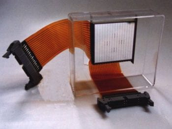
A detail of the cable connection to the Si wafer is shown to the right. The Si wafer is located on the right and it produces a reflection of the cable.
The thin wires making the bonds to the Si strips are seen to the right.

The connection of the thin ribbon cable to the back of a Si wafer is shown to the right.

A one-sided wafer connected to its cable is seen from its front.

A two-sided wafer is seen in front view. It is connected to both cables.
Examples of Energy Spectra and Isotopic Resolution
In the energy calibration of the DE detectors with a 228Th an a source, an energy resolution (FWHM) of 34 keV at 5.684 MeV was easily obtained. This resolution was obtained at the end of an experiment after the 28 mg/cm2 protective Pb absorbers were removed. A (GIF 13 kB) spectrum of this calibration for one of the Si strips can be seen here (alpha spectrum).
Examples of isotopic resolution of intermediate mass fragments is included here: DExE map as a PDF file. 1,2,3H, 3,4,6He, 6,7,8,9Li, 7,9,10Be, and 14,15,16N, isotope resolution is clearly seen. The data are from the reaction of 11 MeV/A 60Ni on 100Mo. The hydrogen and He isotopes punch through significantly, while the Li isotopes punch through to a lesser extent.
The Si Wall with the Microball in Gammasphere
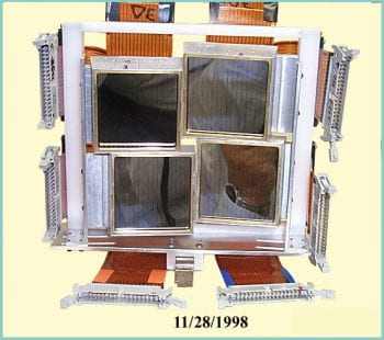
The Wall consists of four DExE Si telescopes mounted in a special arrangement that packs closely around the beam axis.
The Si Wall is seen straight-on. The DE and E detectors are connected to their cables and are mounted in the support structure that allows positioning at the beam exit from the Microball. Note the staggered arrangement and the 2-axes tilt of the detectors under closest possible packing.
Next we have to put it in front of the Microball and in the chamber.
Oh Sh.., it does not fit! The cables are not long enough. Now what?
Well, we put it too far downstream and the cables will not reach. No problem, move the Si Wall back and closer to the Microball where it should be.

Wow, it does fit!
A photograph showing the Si Wall and the Microball in the Gammasphere chamber. This is a back view showing the entrance collimator. The twisted pair cables bring the Si signals out. The cables are exiting the chamber from a backward angle. The beam enters from the left.
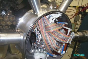
Another photograph showing the Si Wall and the Microball in the Gammasphere chamber. This is a front view showing the Wall a little better.
Crowded isn’t it? The twisted-pair cables bring the Si signals out. The cables are exiting the chamber from a backward angle. The beam enters from the right.

Now everything is connected, buttoned up and ready to go. A photograph showing the Si Wall and the Microball all in the Microball chamber. The Si-Wall tube (left) has a cylindrical enclosure outside the Gammasphere Al shell that houses the preamplifiers. They get quite hot, so air is pumped into the cylindrical housing providing adequate cooling of the preamplifiers. The exit holes for the cooling air can be seen in the high resolution picture.
A few of the neutron detectors are barely seen on the front of the Gammasphere. The beam enters from the left.

Signal Processing and Acquisition
Due to our rather high density specially designed electronics the setup is very compact. This is primarily due to the Shaper-Discriminator modules. They were designed and constructed by Jon Elson at Washington University.
The Washington Universtiy Shaper-Discriminator Modules
The Washington-University Shaper-Discriminator module is a variant of the Microball signal processing module adapted for Si detectors. It contains all the necessary functions for 16 detectors (here strips).
The modules are constructed on two 6-layer boards to a size suitable for CAMAC crates ferom where they receive power and are read or downloaded with gain and threshold information.
The modules have a base line restorer and an adjustable pole-zero correction for each detector channel. In addition, the following functions for 16 channels are available as outputs in a 34-pin connector:
- Preamplifier Inputs via a ribbon 34 pin connector.
- Leading edge discriminators, with computer controlled or settable thresholds.
- Linear outputs through a dual shaper. The amplitude of each channel is adjustable via computer controlled attenuators.
- Attenuated linear outputs from the shaper, with computer controlled gain. The attenuated signal is at preselected fixed ratio to the other linear output. This feature allows for low-gain and high-gain processing via separate ADCs.
- Time-to-FERA converter outputs for digitizing the individual discriminator times.
- ECL discriminator outputs for each channel.
The following functions are available as outputs in LEMO connectors:
- The 16-channel discriminator logical OR.
- A 16-detector multiplicity output.
- A discriminator logical Test output for the computer selected channel.
- A linear test output for the computer selected channel.
The modules are controlled via an interface to a PC.
Eight of the Washington-University Shaper-Discriminator modules sufficient to process all the signals from the Si Wall.

Logic and Digitization
In addition to the one CAMAC crate with the Shaper-Discriminator modules, another crate is needed with 16 FERA ADCs. These include 4 FERAs each for the E, the DE, the E times, and the DE times.
One NIM crate with the delay-and-gate generators needed to providing the ADC gates completes the setup.
Here Bob Charity and Matt Devlin are checking out the Si-Wall signals. Behind Bob are the Neutron detector FERAs. Left of the oscilloscope is the Microball rack of electronics and on its right is the rack with the modules (1 CAMAC crate) and the FERA ADCs (1 CAMAC crate also).
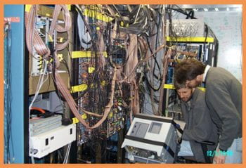
Immediately behind the scope is the Gammasphere electronics rack (FMA not used here). At the center of the picture are the 2 racks with the Microball and the Si-Wall electronics. The rack on the right houses the Neutron detector FERAs. The remaining of the neutron detector electronics are located outside the shack.
Now everything is running so D.G.S. can take pictures.

Milestones of the Silicon Wall
The First Experiment
The Si Wall had its maiden experiment on December 10, 1998. It was used in conjunction with the Microball in an experiment to verify and extend the discrete proton decay from a deformed band in 58Cu to a spherical shell model state in 57Ni. The experiment worked very well and data were obtained with twice the statistics than the earlier experiment that lead to the observation of this effect.
The first experiment performed with the Si Wall and the Microball was:
- (MB-48, GSFMA-42) 141 MeV 36Ar + 28Si (Gammasphere, Si Wall, Microball, Neutron detectors, D. Rudolph, D.G. Sarantites et al.)
- (MB-48A, GSFMA-42A) 12 MeV p + 12C (Si Wall and Microball, stand-alone, Washington U. group). Completed successfully. The calibration of the Si Wall with protons worked very well. The a-particle calibration of the DE detectors showed superb energy resolution (better than 40 keV FWHM at 5.8 MeV).
The setup had 80 Ge detectors in Gammasphere, 20 Neutron detectors and 68 detectors in the Microball (the 3 most forward detector rings were removed). The Si Wall with four DExE 16-strip telescopes covered the 6o – 44o forward angles.
It is to your advantage as a potential Microball user to pay attention to the following restrictions and recommendations that apply when a 4p charged particle array, like the Microball, aims to accommodate a variety of experiments with diverse requirements.
Problems in Running with the Microball – Some Advice
It is well known that no charged-particle detector can survive long if it is hit by elastic scattering. The solution to this problem is to place protective absorbers in front of each CsI(Tl) detector, which is sufficiently thick to stop the most energetic ions of each beam species and yet to be thin enough not to stop most of the protons or alpha particles.
Therefore:
- As an absolute rule, no elastic scattering will be allowed to hit the CsI detectors.
- There is a significant demand for a large variety of reactions and energies to be run with the Microball. Clearly it is not possible to select the optimal absorbers for each Experiment. We will need some understanding that compromises have to be made in an effort to please as many people as possible.
- The factors that must be preserved are :
- Identify the channels as well as possible.
- Measure particle energies as well as possible.
- We must select the absorbers for a “typical reaction“. This means that the absorbers for some reactions will be too thick and for some others too thin.
- We have chosen “The typical reaction” to be: A + B = (Z=50, A=110)* with 5 emitted particles on the average. This establishes the Maximum Energy of Beams that Stop in the Present Microball absorbers. The current list is available here at the bottom of the parameters file.
- Since at the end of each scheduled group of experiments there is some radioactivity deposited on the absorbers of the first ring of detectors, we have often replaced these. On occasion we have changed absorbers somewhat from the standard set when it was deemed that this would improve the data quality for the group of experiments. So make the your calculation as to what the optimal absorber thickness inside the grazing angle is for your reaction and let D. Sarantites (dgs mail address below) know about this well in advance of the scheduling of your experiment.
Restrictions in Running the Microball
We note the fact that 1013 of 50 MeV 12C ions kill the CsI scintillator resolution [see Miersch et al. NIM A369 (1996) 277] with Heavier and more Energetic Ions being worse.
FOR THIS REASON, THE PROCEDURE FOR RUNNING THE MICROBALL MUST BE:
- Limit the Maximum Rate of any type of particle to < 5,000 c/s per detector . This is already too high for a good performance of the Microball, but it is also high enough to keep up with nearly the maximum rates of Gammasphere. Pay considerable attention to the way the Gammasphere dead-time is determined and what fraction of that is comes from the Microball. Understanding this will allow you to do a better experiment, (get more “good” data).
- Set the discriminator thresholds above noise and then look for Excessive Counting Rates in the most forward rings of the Microball. RAISING THE THRESHOLDS TO REDUCE THE APPARENT RATES WILL NOT BE PERMITTED.
- Turning the power to the Microball OFF and RAISING THE BEAM INTENSITY ALSO WILL NOT BE PERMITTED.
Understanding the Absorber problem (?)
Normally one might expect that absorbers may be needed only inside the grazing angle. Experience with all particle detection experiments that run at high beam intensities is that protective absorbers are needed even for the back detectors. The alternative is a lot of noise from target electrons and/or X-rays that are piling up.
To reduce this problem we cover all the Microball detectors with absorbers which are thinner at the back angles. It turns out that the electrons/X-rays strongly increase with beam intensity and Z of the target and Z of the projectile. For high Z targets the situation is a lot better because the Coulomb barrier in general boosts the kinetic energies above the cutoff energy of the absorbers at the back angles. In general we try to use high Z absorbers because they are much more effective in stopping high Z ions relative to low Z ones. Au is the best, but we cannot afford it. Tantalum is next, but rolling it to the desired thickness is very hard. Lead is also good for the thick absorbers, but there are large non-uniformities in rolled lead. Tin-lead allow is only available as 5.0 mg/cm2 and this is not always convenient. This will tell you why in the list of absorbers you will find a variety of metals used.
We never have loss of particles in the front angles for any projectile-target combination. This is not true at the back angles. There, the loss of particles, mainly a‘s, becomes worse with decreasing Z of the target. One the other hand, because the target Z is lower the number of electrons/X-rays is smaller. It is not clear that anyone understands the quantitative solution to this problem.
Another situation in which loss of efficiency and performance appears is in reverse kinematics reactions. As the Zproj/Ztarget approaches and surpasses 1.0 one has to consider each case carefully in estimating expected losses. We will not solve this problem here.
For further information contact: dgs@wustl.edu.
Figure 1.1: Schematic Diagram
Schematic diagram showing a vertical section of the Microball. The number of detectors for each ring are given with bold type. The polar angle theta and the half angle are also given. The detectors are shown in black facing the target, the light guides are shown as blue trapezoids, the diodes are shown in green, and the supporting Delrin rings in shaded red. The detectors are shown attached to the rings via the gold-plated pins (red lines) of the photodiodes.
Figure 1.2: Microball in Gammasphere at LBNL

An overview of one hemisphere of the Gammasphere with the Microball in place.
Figure 1.3: The Microball – Real close

Close-up photograph of the Microball installed in Gammasphere. The Microball detectors are supported by thin Delrin rings which are held by aluminum legs. The supporting structure allowing 9 degrees of freedom (rotations and translations) is used to align the device to the chamber and the beam axis. The detectors are held by rectangular blocks that hold the two leads of the photodiode. The signal cables are thin shielded coaxial cables (75 Ohm) with Teflon insulation and connect the diodes to their preamplifiers located outside the vacuum. Ring 6 is located at exactly 90o and it has an opening to allow the target rod to be inserted in position.
Figure 1.4: Another Close-up of the Microball

Parameters for experiments GS-61, GS-62, GS-63, GS-64, and GS-65
Parameters for experiments GSFMA-19 to GSFMA-22 or MB-41 to MB-44.
The Microball energy calibration for the experiments MB-36 through MB-40 are listed here: Microball calibration from MB-38.
The parameters for experiments MB-41 through MB-44 (or GSFMA-19 through GSFMA-22) are the same as those for MB-36 through MB-40 listed above.
The alpha-particle energy calibration for the remaining experiments can be obtained from the file: Microball alpha calibrations for experiments M-41 through M-44 and beyond. From now on only the proton energy calibration from 12 MeV protons on 12C will be needed. These were done in MB-42 and analyzed. The slopes and intercepts are given in the file here: MB-42-proton-cal-coeff.dat. Get the proton energy in MeV (from channel no. 2048 channels, no compression) and then plug it in the formula above for the alpha energy.
Parameters for experiments GSFMA-39 to GSFMA-41 or MB-45 to MB-47. The calibrations for this group of experiments has been done. Here is the proton coefficients file.
Parameters for experiments MB-49 to MB-52.
For important information about the calibration and analysis of this last group of experiments click here: Latest Experiments and Calibrations
The configuration file for the experments started on October 28, 2001 are listed here as MBALL_A_10_14_01.txt
You will find here a set of Range-energy files for the Microball absorbers as well as for a few target metals. The proton and alpha ranges are listed in sequence in each file. These were calculated from the Ziegler code TRIM 95 and converted to MeV vs. mg/cm2 by D.G.S.
Ranges of Protons and Alphas in Aluminum
Ranges of Protons and Alphas in Lead
Ranges of Protons and Alphas in Tin
Ranges of Protons and Alphas in Tin-Lead
Ranges of Protons and Alphas in Tantalum
Ranges of Protons and Alphas in Nickel Targets
The Neutron Shell was designed especially for use in conjunction with the Gammasphere and often with the Microball for the purpose of selecting one and two neutron evaporation channels in very neutron deficient systems for far from stability gamma-ray spectroscopy. The Neutron Shell consists of up to 30 tapered hexagonal detectors that replace the 30 Ge-BGO modules of the 6 most forward rings of Gammasphere.
- The Design
- The Detectors
- Neutron-gamma Discrimination
- The Neutron Shell in Gammasphere
- Signal Processing and Acquisition
- Milestones of the Neutron Shell
- A NIM paper (in press) describing the Neutron is Available in Preprint form here: Neutron Shell.pdf. ” ‘Neutron Shell’: A high efficiency array of neutytron detectors for g-ray spectroscopic studies with Gammasphere”, D,G. Sarantites, W. Reviol, C.J. Chiara, R.J. Charity, L.G. Sobotka, M. Devlin, M. Furlotti, O.L. Pechenaya, J. Elson, P. Hausladen, S. Fischer, D. Balamuth, and R. M. Clark, Nucl. Instrum. and Methods, (in press 2004).
The Design
The design of the geometry of the Neutron Shell for Gammasphere is dictated by the constaints imposed by the geometry of Gammasphere. A series of Monte Carlo simulations were performed by the LBL and the University of Pennsylvania groups using the code GEANT.
It was concluded that the optimal cost effective solution is to approximate the BGO elements with a uniform regular tapered hexagonal geometry that packs on the average as well as possible.
A schematic representation of the shell is seen here. (a) Shows a side view of the Shell and (b) the front view as the beam or neutrons see it.

A photograph of the left hemisphere of the Neutron Shell is seen here. The 8 mm Pb absorbers are seen painted green. The 1.2 mm Al hexagonal containers are painted red. The expansion bellows have not been installed at this time.

The Detectors
Here is the first working detector.
The design of the neutron detectors was done by D. Sarantites. The construction plan was produced in close consultation with Jim Linders of the Washington University Chemistry department machine shop.
First, the detector housing was made from tapered spun funnels made of 1.2 mm thick aluminum.
A close-up photograph of a funnel is seen here. It was first spun, but the spinning process did not produced sufficiently uniform thicknesses. Then the funnels were machined to uniform thickness, and cut to the appropriate length.

A close-up photograph of a funnel being pressed into a hexagonal can is seen here. A pressure of 2,000 atm was applied to bring the can into the desired shape.

The hexagonal cans were cut to the exact designed length. Then the bottom of the can was welded on. It has the appropriate shape and it is sufficiently thick to allow tapped threads to be made that will support the Pb absorbers with 6 screws.
The top hexagonal flanges are the most important part of the detector housing. They have appropriate grooves for the quartz windows to be held for sealing. Also the provide the tight fit for the µ-metal shields. They also have the threads for the three support rods that connect the detectors to the BGO-like flanges that in turn couple to the Gammsphere shell.
Forteen of the cans are seen here. They have been painted on the inside with the TiO2 based epoxy-type reflector. If you are using Netscape, right click and choose “View Image” to see the picture with more resolution.
The Assembly
The final assembly is done as follows:
- The 3.2-mm thick quartz windows were glewed with torrseal to make an air tight seal. The use of Araldite is not recommended because with the BC-501A scintillator turns yellow and in colors the scintillator solution. This is detrimental to the PSD for neutrons and gammas.
- Initially the detector volume was filled with BC501A scintillator liquid. There is a threaded opening the allows for the filling. A bubble with a volume of about 70 cm3 was left in the container for thermal expansion in the fist round of experiments.
- Then the liquid was bubbled with Ar gas to remove any dissolved oxygen. Approximately, 100 psi of pressure drop from a large compressed bottle was used. The procedure took about 24 hours. Three detectors were bubbled at a time via a manifold.
- The light guides were then optically coupled to the window using optical silicone based grease. The light guide consist of UVT (UV-transparent lucite). One side is flat to couple to the window and the other is spherical with the radius that matches the curvature of the PMT.
- The 5-inch diameter (RCA-8854) PMT’s are then coupled to the light guides again with silicone grease. The PMT’s have are covered on the sides with sufficiently thick electrical insulation that will permit running these tubes with negative voltage.
- The magnetic shield are inserted next to the top of the flange. There is a black felt tape that wraps the narrow end of the PMT’s that prevents light from entering the photocathode area.
- The voltage dividers were connected next and were aligned so that the alignment gap coincided with the filling position. This allowed easy attachment of the expansion bellows later on.
- After the first group of experiments the expansion bellows were connected. First, the liquid scintillators were rebubled with Ar as before. Then the bellows were aligned and hermetically connected. The bellows were then filled with BC501A scintillator that was also bubbled with Ar to remove traces of oxygen. The bellows are excellent thermometers! They expand or contract by about 1.1 mm per oC or 0.62 mm per oF.
Neutron-gamma discrimination
The Neutron Shell for Gammasphere provides a multitude of methods for neutron-gamma discrimination.
- Time of flight relative to the accelerator RF.
- Zero-crossing time relative to the RF.
- Pulse shape discrimination using a total gate on the low gain and a late gate on the high gain signal.
- Time over threshold of the zero crossing discriminator. This is a derived quantity obtained by subtracting the ToF signal for a given pulse height from the Zero crossing one.
- Use of two gains, low and high, differing by a factor of about 5 in gain increases the dynamic range considerably. This enhance the efficiency of the array for the abundant low energy neutrons.
A preliminary set of PID maps is shown here. The panels are self explanatory. The source is 252Cf with the start from a CsF fast scintillator. For in beam samples of maps please wait after the New Millennium starts.

The Neutron Shell with the Microball in Gammasphere
The Neutron shell and the Microball in Gammasphere are seen here. The neutron detectors are colored red while their 8 mm Pb absorbers were painted green. The Microball chamber is open on both sides. Only half of the Neutron Shell is visible in this hemisphere with 16 detectors in place. The beam enters from the right. The FMA quadrupole magnet is seen on the left in blue. 
Signal Processing and Acquisition
The best operation of the Neutron Shell relies on the use of the excellent timing resolution of the ATLAS accelerator. Typically 1.0 ns FWHM is easily archived after minimal effort with re bunching. The start of the timing is made by the RF enabled by the Gammasphere Pre-trigger timing signal.
The setup provides for a convenient and easy way to align the times from the zero-crossing discriminators. Since the latter timing can be made essentially pulse height independent it is possible to apply a hardware veto for the gamma flash within the time required to provide the external bit for the neutron array. The result is that for mixed triggers (n-g-g) + (g-g-g-g) for example, the computer dead time is reduced substantially. This enriches the data set in the desired neutron coincidences by 30-40%. The alignment of the times is done with programmable ECL delays.
This is a schematic diagram of the electronics for the Neutron-Shell setup of the 9 experiments done at ATLAS with the Gammasphere, Microball and the Neutron Shell. The diagram is almost self explanatory. Sorry, but all the Module models are not given.
Milestones of the Neutron Shell
The Neutron Shell had its maiden experiment on September 27, 1999. It was used in conjunction with the Microball in an experiment to search for new structures below the 60Zn. The experiment worked very well and data were obtained. Also the performance and tuning of the array was done. The hardware gamma veto was implemented and worked satisfactorily.
The first group of experiments performed with the Neutron Shell and the Microball was:
- (MB-53, NS-1, GSFMA-73) 130 MeV 32S + 28Si (Gammasphere, Neutron shell, Microball, D.G. Sarantites et al.) Completed succesfully.
- ((MB-54, NS-2, GSFMA-74) 100 MeV 32S + 40Ca (Gammasphere, Neutron shell, Microball, FMA) P. Fallon et al. Completed succesfully.
- (MB-55, NS-3, GSFMA-74) 145 MeV 36Ar + 40Ca (Gammasphere, Microball, Neutron shell, FMA) P.Fallon et al. Completed successfully.
- (MB-56, GSFMA-75) 12 MeV p + 12C (Microball, stand- alone, Washington U. group). Completed succesfully.
- (MB-57, NS-4, GSFMA-76) 185 MeV 40Ca + 58Ni, (Gammasphere, Microball, Neutron Shell, FMA), B. Cederwall et al., Completed succesfully.
- (MB-58, NS-5, GSFMA-77)125 MeV 40Ca + 40Ca, Gammasphere, Microball, Neutron Shell, no FMA, S. Paul et al.. Canceled because the operations lost the 40Ca in the ion source!!!
- (MB-59, NS-6, GSFMA-78)Beam 225 MeV 58Ni + 50Cr, Gammasphere, Microball, Neutron Shell, no FMA, C. Baktash et al. Completed succesfully.
- (MB-58A, NS-5A, GSFMA-77) 125 MeV 40Ca + 40Ca, Gammasphere, Microball, Neutron Shell, no FMA, S. Paul et al. Repeated and done succesfully.
- (MB-60, NS-7, GSFMA-79) 260 MeV 64Zn + 64Zn, Gammasphere, Microball, Neutron Shell, and FMA, D. LaFosse et al. Completed succesfully.
- (MB-60, NS-8, GSFMA-80) 235 MeV 58Ni + 58Ni, D. Seweryniak et al.(Microball, Neutron Shell, Si detectors)Succesfully attempted.
- (MB-61, GSFMA-81) 12 MeV p + 12C (Microball, stand- alone, Washington U. group). Completed
- (MB-62, NS-9, GSFMA-82) 207 MeV 54Fe + 58Ni, D. G. Sarantites et al.(Microball, Neutron Shell, Si cube) Completed. Lots of accelerator trouble: lost beam time
This marks the first and last Microball + Neutron shell experiments with Gammasphere at ATLAS.
The Neutron detector gain matching was done approximately with the 2615 keV gamma from a 228Th source. The edge of that gamma was placed at approximately channel 1900 in the high gain energy spectra. It corresponds to about 6 MeV in neutron energy.
For the calibration files of the Microball from MB-55 see the Microball home page.
The setup had 78 Ge detectors in Gammasphere, 30 Neutron detectors and 94 out of 95 working detectors in the Microball. In experiment MB-56 the detector 14 fixed “itself”. From then on all 95 out 95 detectors in the Microball work.
The configuration file for the Neutron Shell contains angles and positions of the neutron detectors in Gammasphere. Configuration file for the Neutron Shell.
The time stability of the Neutron Detector timing relative to the RF was monitored for each experiment. It was found to be very good. In NS-3 and NS-4 the timing of detector 11 was jumping with time. Later on it was stabilized. All detectors resolve the gamma rays from the neutrons by 3 methods and 4 ways.
The Microball was designed and constructed by the group of D.G. Sarantites.