The Different Parts of the System
This launcher has 3 main parts. The Raspberry Pi 3b+, the single flywheel launcher, and the pitch-yaw axis robot. The Raspberry Pi served as the brains of the system. It contained all the code from commanding the Pi Camera to take an image to doing the calculations for the correct pitch and yaw angles and driving the Teknic ClearPath Step and Direction motors to those angles.
The single flywheel launcher was a pitching machine from PowerAlley Lite that we purchased from Amazon. The projectiles we used were baseballs that came with the pitching machine from PowerAlley.
The pitch-yaw axis robot was a robot provided to us by our Capstone advisor, Professor Mell. It contains two Teknic ClearPath step and direction motors, with one motor controlling the pitch, or up and down rotation, and the other controlling the yaw, or the side-to-side rotation. A 3.3V to 5V level converter allowed us to control the motors with the Raspberry Pi.
System Process
The first part of the process deals with image processing. For our project, we targeted blue squares on a wall. When the launcher was facing the wall, the Raspberry Pi commanded the Pi Camera that was mounted on the front of the robot to take a picture. That picture came back to the Pi for image processing to find the blue squares. We applied masks to the image using HSV values for the specific color of blue we were looking for. To improve our accuracy, and filter out unwanted blue colors, we blurred the image, and then morphed nearby filtered objects into one another. Finally, we used OpenCV’s contour function to find multiple blue squares in one photo, and put the x and y values of the coordinates that represented the center of the blue squares.
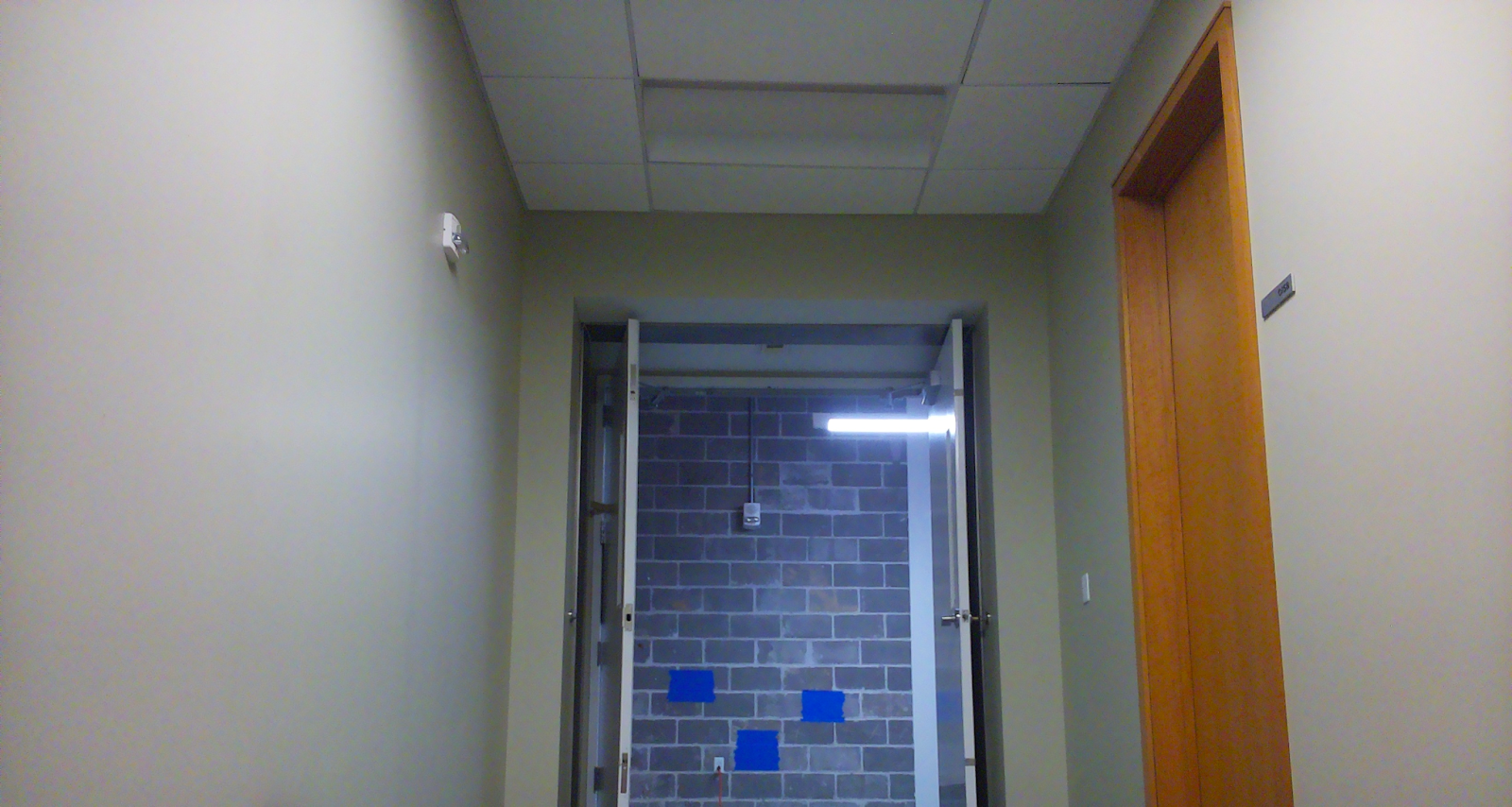
Original Photo of Targets Captured by Raspberry Pi Camera Module

Filtered Mask of the Blue Targets in the Image
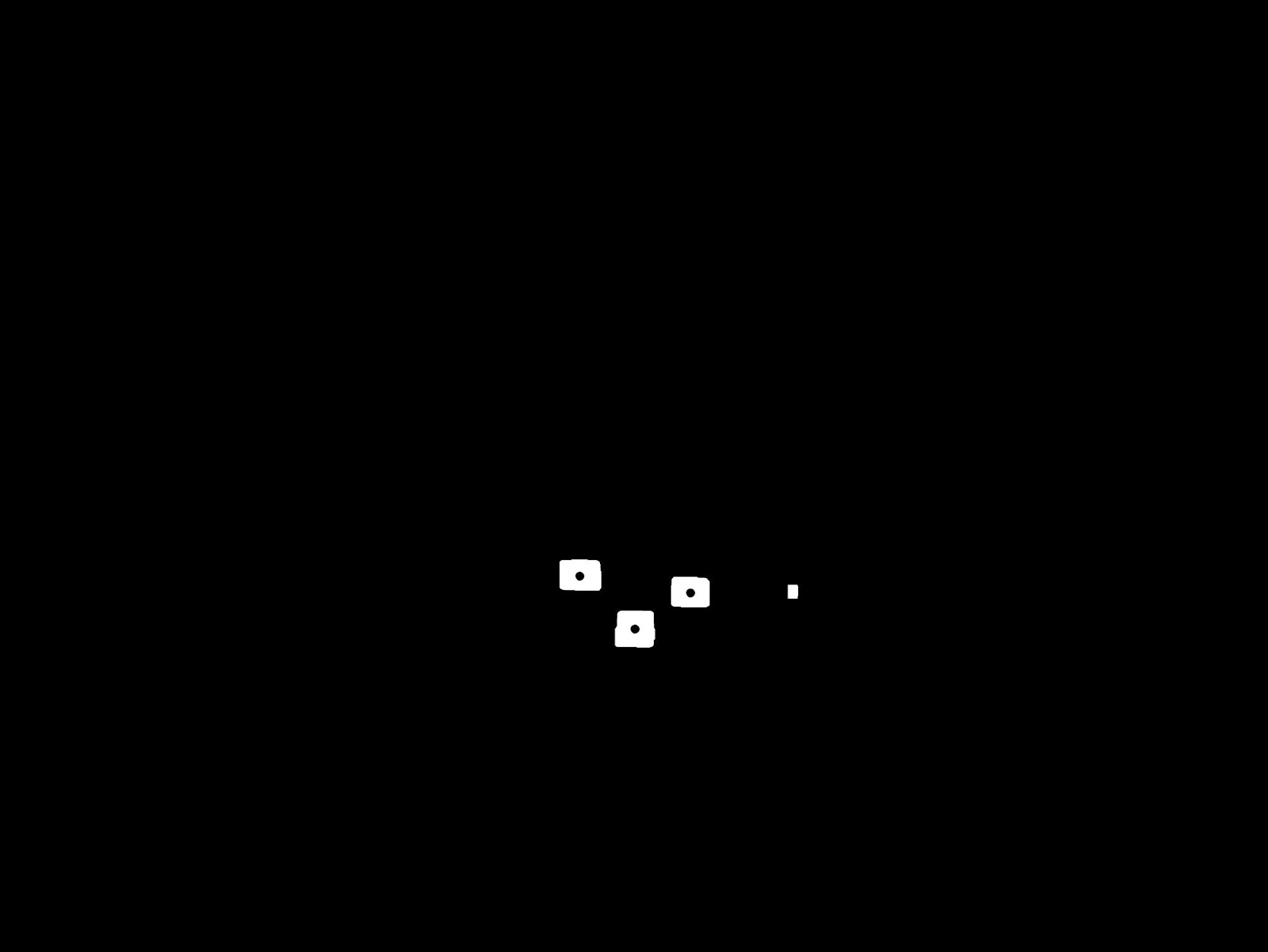
Multiple Identified Center Points using OpenCV
The second part of the process involved physics calculations. Those x and y values for the blue squares were fed into a function that calculated the pitch and yaw angles for the robot for every square it found. The yaw angle was found simply by forming a right triangle, with the two sides being the distance from the launcher to the wall and the horizontal distance from the launcher to the individual target. The hypotenuse was the true distance from the launcher to the target. The yaw angle was the inverse tangent of the horizontal distance from the launcher to the target divided by the distance from the launcher to the wall. The pitch angle was solved for by heavy algebraic manipulation of the x and y direction projectile motion equations.
After the pitch and yaw angles were found, the third major step was to command the motors on the pitch-yaw axis robot to turn to the correct angles. This was done by feeding the calculated pitch and yaw angles into functions we created that turn the motors to those angles by assigning a certain number of steps per degree for the motors and keeping track of the steps for each motor until it reached our desired number of total steps. Once the launcher is in position, we are ready to fire a projectile!
Feedback for target hitting is dependent on the user. If the target is hit, the user can tell the launcher to aim at the next target. If the target is missed, we have 4 commands the user can enter based on if the launcher needs to move up, down, left, or right by a degree. These inputs can be used multiple times. For example, the user can move the launcher left two degrees and up one degree after one shot. Once the user is satisfied, they can once again move to the next target.